
User Guide


Start-Up/
Commissioning
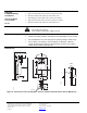
Non-spring Return
Modulating Control
(0 to 10 Vdc)
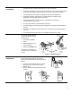
24 Vac
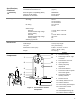
1.
Check Operation:
a. Connect wires 1 (red) and 2 (black) to the 24 Vac power supply.
b. Set the Digital Multimeter (DMM) dial to Vdc for the actuator input signal.
c. Connect wires 2 (black) and 8 (gray) to a Digital Multimeter (DMM).
d. Apply a full-scale input signal (10 Vdc) to wire 8 (gray).
e. Allow the actuator shaft coupling to rotate from 0 to 90°.
f. Stop the signal to wire 8 (gray).
The shaft coupling returns to the "0" position.
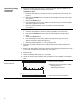
2. Check Feedback:
a. Set the DMM dial to Vdc.
b. Attach wires 2 (black) and 9 (pink) to the DMM.
c. Apply a full-scale input signal to wire 8 (gray).
The reading at the DMM should increase.
d. Remove the signal from wire 8 (gray).
The reading at the DMM should decrease and the actuator shaft coupling returns to the
"0" position.
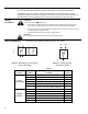
3. Check Auxiliary Switch A:
a. Set the DMM dial to ohms (resistance) or continuity check.
b. Connect wires S1 and S3 to the DMM.
The DMM should indicate open circuit or no resistance.
c. Apply a full-scale input signal to wire 8 (gray).
The DMM should indicate contact closure as the actuator shaft coupling reaches the
setting of switch A.
d. Connect wires S1 and S2 to the DMM.
The DMM should indicate open circuit or no resistance.
e. Stop the signal to wire 8 (gray).
The DMM should indicate contact closure as the actuator shaft coupling reaches the
setting of switch A.
4. Check Auxiliary Switch B:
a. Set the DMM dial to ohms (resistance) or continuity check.
b. Connect wires S4 and S6 to the DMM.
The DMM should indicate open circuit or no resistance.
c. Apply a full-scale input signal to wire 8 (gray).
The DMM should indicate contact closure as the actuator shaft coupling reaches the
setting of switch B.
d. Connect wires S4 and S5 to the DMM.
The DMM should indicate open circuit or no resistance.
e. Stop the signal to wire 8 (gray).
The DMM should indicate contact closure as the actuator shaft coupling reaches the
setting of switch B.
Page 9