
User Guide
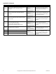


Table Of Contents
- Application
- DuraDrive™ Direct Coupled Actuators are designed to be used in both damper and valve control applications. The following general instructions are for damper applications. Refer to the Applicable Literature table for valve literature.
- The MS4X-7XX3 series spring return actuators provide proportional modulation control of dampers and valves in HVAC systems.
- Features
- . Proportional models controlled by 6-9 Vdc, 2-10 Vdc, or 4-20 mA with the addition of a 500 ohm resistor
- . 133 lb-in (15 N-m), 60 lb-in (7 N-m) or 35 lb-in (4 N-m) of torque
- . Rugged die-case housings rated for NEMA 2 / IP54
- . Optional built-in auxiliary switch to provide for interfacing or signaling
- . Provides 95° of rotation
- . Visual position indicator provided
- . Provides true mechanical clockwise or counterclockwise spring return operation for reliable fail safe application and positive close-off in air tight damper applications
- . MS40-7043-MPX models controlled by 6-9 Vdc with auxiliary 20 Vdc power supply provides power to controllers, replacing MP-5XXX/MPR-5XXX electrohydraulic actuators
- . Direct mount to round or square damper shafts
- . Switch provided for selection of direct or reverse acting control mode
- . Rotation limiting available
- . MS4X-7153 series actuators can be double- mounted (gang mounting) to accommodate high torque application requirements
- . Five year warranty
- . MS41-7073 and MS41-7153 equipped with manual override
- Applicable Literature
- SPECIFICATIONS
- TYPICAL APPLICATIONS (wiring diagrams)
- INSTALLATION
- Inspection
- Requirements
- Precautions
- Canadian Department of Communications (DOC)
- Jackshaft Installation
- Wiring Requirements
- Rotation Limitation
- Rotation Limitation for MS40-7043 Series
- 1. Determine the amount of damper rotation required. The actuator stop block provides limited rotation from 40˚ to 95˚.
- 2. Loosen the screw securing the stop block to the actuator.
- 3. Slide the stop block into position, so that its edge lines up with the degree graduation on the actuator face which corresponds with the required rotation. See Figure-5.
- 4. Secure the stop block in place.
- 5. Test the damper rotation by applying power and the required control signal. Re-adjust if necessary.
- Figure-5 Adjusting Stop Block for Limited Rotation.
- 1. Determine the amount of damper rotation required. The actuator stop block provides limited rotation from 40˚ to 95˚.
- Rotation Limitation for MS4X-7153 and MS4X-7073 Series
- 1. Determine the amount of damper rotation required.
- 2. Locate the AM-689 rotation limiter on the actuator so that its edge lines up with the degree graduation on the actuator face which corresponds with the required rotation. See Figure-6.
- 3. Find the appropriate cross-hair location through the slot of the rotation limiter. This is the mounting location for the retaining screw.
- 4. Pierce through the label material to allow easy fastening of the retaining screw.
- 5. Position the rotation limiter back to the desired position, making sure the locating “teeth” on the rotation limiter are engaged into the locating holes on the actuator.
- 6. Fasten the rotation limiter to the actuator using the self-tapping screw provided.
- 7. Test the damper rotation by applying power and the required control signal. Re-adjust if necessary.
- Figure-6 Securing the AM-689 Rotation Limiter.
- 1. Determine the amount of damper rotation required.
- Minimum Damper Positioning
- 1. Position the damper to its minimum position by providing the appropriate control signal to the MS4X-7073 or MS4X-7153.
- 2. Place the position indicator onto the actuator spline in the approximate position shown in Figure-7. Fasten it with the retaining clip.
- 3. Place the AM-689 rotation limiter on the actuator so that it either makes contact with, or is as close as possible to, the edge of the indicator. See Figure-8.
- 4. Make sure that the locating teeth are engaged into the locating holes on the actuator. If all of the mounting teeth do not al...
- 5. Find the cross-hair location through the slot of the rotation limiter. This is the mounting location for the retaining screw.
- 6. Pierce through the label material to allow easy fastening of the retaining screw.
- 7. Fasten the rotation limiter to the actuator using the self tapping screw provided.
- 8. Test the damper operation by applying power and the required control signal. Re-adjust if necessary.
- Figure-7 Installing the Position Indicator.
- Figure-8 Positioning the Rotation Limiter.
- 1. Position the damper to its minimum position by providing the appropriate control signal to the MS4X-7073 or MS4X-7153.
- Rotation Limitation for MS40-7043 Series
- CHECKOUT
- MAINTENANCE

Printed in U.S.A. 1/10 © Copyright 2010 Schneider Electric All Rights Reserved. F-26645-8
Application
DuraDrive™
Direct Coupled Actuators are designed to
be used in both damper and valve control applications.
The following general instructions are for damper
applications. Refer to the Applicable Literature table for
valve literature.
The MS4X-7XX3 series spring return actuators provide
proportional modulation control of dampers and valves
in HVAC systems.
Features
• Proportional models controlled by 6-9 Vdc, 2-10
Vdc, or 4-20 mA with the addition of a 500 ohm
resistor
• 133 lb-in (15 N-m), 60 lb-in (7 N-m) or 35 lb-in
(4 N-m) of torque
• Rugged die-case housings rated for NEMA 2 / IP54
• Optional built-in auxiliary switch to provide for
interfacing or signaling
• Provides 95° of rotation
• Visual position indicator provided
• Provides true mechanical clockwise or
counterclockwise spring return operation for reliable
fail safe application and positive close-off in air tight
damper applications
• MS40-7043-MPX models controlled by 6-9 Vdc with
auxiliary 20 Vdc power supply provides power to
controllers, replacing MP-5XXX/MPR-5XXX
electrohydraulic actuators
• Direct mount to round or square damper shafts
• Switch provided for selection of direct or reverse
acting control mode
• Rotation limiting available
• MS4X-7153 series actuators can be double-
mounted (gang mounting) to accommodate high
torque application requirements
• Five year warranty
• MS41-7073 and MS41-7153 equipped with manual
override
MS40-7043 Series
MS4X-7073 Series
MS4X-7153 Series
DuraDrive Series Spring Return
Proportional Actuator
General Instructions
MS40-7043
MS40-7043-501
MS40-7043-MP
MS40-7043-MP5
MS40-7073
MS40-7153
MS40-7073-502
MS40-7153-502
MS41-7073
MS41-7153
MS41-7073-502
MS41-7153-502