
User Guide


6 © Copyright 2008 TAC All Rights Reserved. F-27120-5
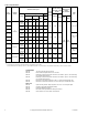
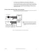
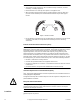
TYPICAL FLOATING CONTROL (wiring diagrams)
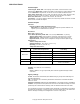
Figure-2 through Figure-5 illustrate typical wiring diagrams for MFx1-7203 Series spring
return floating actuators. See Table-1 for model selection.
Caution:
This product contains a half-wave rectifier power supply and must not be
powered off transformers used to power other devices utilizing non-isolated full-wave
rectifier power supplies. Refer to
EN-206, Guidelines for Power Multiple Devices from a
Common Transformer, F-26363
for detailed information.
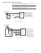
MF51-7203
MF61-7203
24 Vac Transformer
or 22-30 Vdc
Red
Black
Common
1
Hot (+DC)
Line
Volts
Blue
Extend
Retract
Yellow/Black
1 Provide overload protection and
disconnect as required.
2 Actuators may be wired in parallel.
All actuator black wires are
connected to the transformer
common and all red wires are
connected to the hot lead. Power
consumption must be observed.
2
Green/Yellow
Typical
Floating
Controller
Figure-2 Floating Point Control.
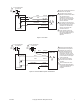
MF51-7203
MF61-7203
24 Vac Transformer
or 22-30 Vdc
Red
Black
Common
Hot (+DC)
1
Line
Volts
Controller
Blue
1 Provide overload protection
and disconnect as required.
2 If the controller uses a full-
wave power supply and does
not provide isolated outputs, a
separate transformer is
required.
3
Yellow/Black
Hot
Common
Green/Yellow
Extend
Retract
2
Actuators may be wired in parallel.
All actuator black wires are
connected to the transformer
common and all red wires are
connected to the hot lead. Power
consumption must be observed.
3
Figure-3 Triac Source.