
User Guide


F-27120-5 © Copyright 2008 TAC All Rights Reserved. 9
INSTALLATION
Inspection Inspect the package for damage. If damaged, notify the appropriate carrier immediately. If
undamaged, open the package and inspect the device for obvious damage. Return
damaged products.
Requirements • Job wiring diagrams
• Appropriate accessories
• Pliers for removing and inserting connecting pin
• Installer must be a qualified, experienced technician
• Tool-37, 1-1/2" to 3" adjustable spanner wrench for valve mounting nut
• 5/16" (Tool-20-1) and 3/4" open-end wrench for stem jam nuts
• 1/8" Allen wrench
• Size 10 IP Torx Plus bit (Mx51 units only)
Precautions General
Warning:
• Electrical shock hazard! Disconnect the power supply (line power) before installation to
prevent electric shock and equipment damage.
• Make all connections in accordance with the job wiring diagram and in accordance with
national and local electrical codes.
Use copper conductors only.
• Floating and Proportional Models: These products contain a half-wave rectifier power
supply. They must not be powered with transformers that are used to power other
devices utilizing non-isolated full-wave rectifier power supplies. Refer to EN-206,
Guidelines For Powering Devices From A Common Transformer, F-26363 for detailed
information.
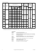
Red
Blk
Com
Hot (+DC)
Line
Volts
(-)
(+)
Yel/Blk
AI
Red
Blk
Com
Hot (+DC)
Yel/Blk
AI
Blu
AO
2
MSX1-7203
L R
MSX1-7203
L R
Com
Gra
Com
Gra
Grn/Yel
Grn/Yel
1
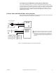
Two Actuators Wired in Parallel
Control Signal
2 to 10 Vdc
24 Vac
Transformer
or 22- 30 Vdc
2
1 Provide overload protection and disconnect
as required.
2 To reverse actuator control function
(direct/reverse action), use the reversing
switch, see Figure-9.
Figure-7 Typical Wiring Diagrams for Proportional Control 24 Vac Models Wired in Parallel.