
Install Instructions
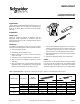
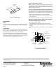
Table Of Contents
- MOUNTING
- 1. Select the position required.
- 2. Remove the selected housing screw.
- 3. Slide the positioner over the screw post and securely reinsert the screw.
- 4. Unthread the clevis or ball joint from the actuator shaft.
- 5. Align the holes in the feedback arm (Figure-1) and the shaft fitting.
- 6. Insert the threaded end of the shaft fitting through the appropriate hole in the feedback arm, and rethread the fitting into the output shaft. Do not tighten securely.
- 7. Remove the appropriate spring from the kit. (Refer to Table-1 for selections.) Hook one end of the spring onto the positioner (Figure-2) and the other end into the spring hole in the end of the feedback arm (Figure-1).
- 8. Align the feedback arm so that the spring is perpendicular to the positioner.
- 9. Tighten the shaft fitting securely to the output shaft.
- PIPING
- START POINT
- ADJUSTABLE NEEDLE-VALVE

Copyright 2010, Schneider Electric
All brand names, trademarks and registered
trademarks are the property of their respective
owners. Information contained within this
document is subject to change without notice.
F-23937-4
www.schneider-electric.com/buildings
Schneider Electric
1354 Clifford Avenue
P.O. Box 2940
Loves Park, IL 61132-2940
On October 1st, 2009, TAC became the Buildings business of its parent company Schneider Electric. This document reflects the visual identity of Schneider El ectric,
however there remains references to TAC as a corporate brand in the body copy. As each document is updated, the body copy will be changed to reflect appropriate
cor
p
orate brand chan
g
es.
Figure-1 Feedback Arm.
Adjustments
SPAN
The signal pressure change required to produce full actuator
stroke is determined by the feedback spring. Select the spring from
Table-1.
START POINT
Refer to Figure-2. The signal pressure at which the actuator shaft
begins to move is adjustable from 3 to 12 psig by rotating the
recessed brass knurled dial in the center of the positioner.
The start point of the actuator may be adjusted by setting the signal
pressure to the desired value and turning the recessed knurled
wheel by hand until the actuator shaft begins to move. Turning the
wheel outward toward the spring raises the start point.
ADJUSTABLE NEEDLE-VALVE
Refer to Figure-2. The needle-valve allows the adjustment of the
rate of actuator movement. With this needle-valve, the speed of
the M556, M573, and M574 actuators may be adjusted with a small
blade screwdriver, if required, to:
Give the actuators the same relative rate of movement
This makes it possible, for example, to have outside, return, and
relief dampers on an air handling unit move together, rather than
at different rates. This is especially important at the following times:
• When large air handling units are started and stopped.
• When dampers are switched from “summer” to “winter” opera-
tion or the reverse.
Both of the above examples can cause large damper movements.
Adjust the actuators to move slowly so that a narrower
controller throttling range can be used
This is important for the following:
• Controlling supply air static pressure with a vortex damper.
• Controlling mixed air temperature with outside, return, and relief
dampers.
• Controlling space static pressure with one or more relief damp-
ers.
Figure-2 Positioner Adjustment
and Port Connections.
Feedback
M573
Spring
M574
M556
Actuator
Housing Screw
M (20 psi Main Air)
B (Output
to Actuator)
Adjustable
Needle-Valve
Start Point
Adjustment Dial
S (3-15 psi
Signal Input)
Feedback
Spring
Connection