
Overview of Primary Product
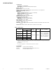
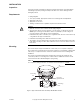
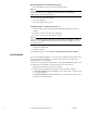
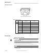


Table Of Contents
- Application
- Features
- Applicable Literature
- SPECIFICATIONS
- INSTALLATION
- Mounting
- ADJUSTMENTS
- MAINTENANCE
- MAINTENANCE PARTS
- Figure-2 MK-46xx Maintenance Parts.
- 1. Disconnect air line to actuator.
- 1. Disconnect air line to actuator.
- 2. Rotate start point adjustment counterclockwise (as viewed from the bottom) to remove as much spring compression as possible.
- 3. Remove the four cover mounting screws, the top cover, and the diaphragm.
- 4. While holding down the piston with the heel of your hand, remove the connecting pin.
- 5. Slowly release pressure on piston and remove piston.
- 6. Remove spring and insert replacement.
- 7. Position piston over spring, making sure position indicator is aligned with guide.
- 8. Pushing down on piston, align holes in valve stem extension and piston shaft and insert connecting pin.
- 9. Position diaphragm and top cover on actuator and even secure with the four screws.
- 10. Refer to "ADJUSTMENTS" on page 4 and adjust start point of actuator to desired value.
- MK-46xx Series
- MK4-46xx Series
- MK-46xx Series
- MAINTENANCE PARTS

F-13894-7 © Copyright 2006 TAC All Rights Reserved. 3
INSTALLATION
Inspection
Inspect the package for damage. If damaged, notify the appropriate carrier immediately.
If undamaged, open the package and inspect the device for obvious damage. Return
damaged products.
Requirements
• Piping diagrams.
• Tools (not provided): Appropriate wrenches for mounting bolts and adjustments.
• Appropriate valve body.
• Appropriate accessories.
• Training: Installer must be a qualified, experienced technician or fitter.
Caution:
• Make all connections in accordance with the piping diagram.
• Avoid locations where excessive moisture, corrosive fumes, or vibration are present.
NEMA Type 1 housings are intended for indoor use primarily to provide a degree of
protection against contact with the enclosed equipment.
• Install all two-way valves so that they close against the flow. An arrow on the valve body
or tag indicates the proper flow direction.
• Install three-way mixing valves with two inlets and one outlet.
• The actuator can be mounted in any position above the horizontal centerline of the valve
body. When selecting a location, allow sufficient room for accessories and for service of
the product.
Mounting
The actuator may be shipped assembled to a valve body or as a separate component.
These instructions are intended for use where the actuator is to be installed to a linkage and
valve body, as a replacement unit, or when the actuator must be removed during valve
installation.
The actuator is generally installed in an upright position and may be swivelled to any
convenient position for connecting to the control air line. In addition the actuator can be
removed from the valve with disturbing the spring setting.
N O T E
For complete mounting instructions, see AV-401 General Instructions, F-25586.
Mounting
Nut
Air
connection
Start point
adjustment nut
Connecting
Pin
Figure-1 Typical Pneumatic Valve Assembly with MK-46xx Actuator.