
Overview of Primary Product
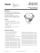
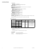
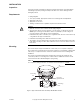
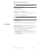
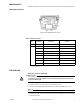


Table Of Contents
- Application
- Features
- Applicable Literature
- SPECIFICATIONS
- INSTALLATION
- Mounting
- ADJUSTMENTS
- MAINTENANCE
- MAINTENANCE PARTS
- Figure-2 MK-46xx Maintenance Parts.
- 1. Disconnect air line to actuator.
- 1. Disconnect air line to actuator.
- 2. Rotate start point adjustment counterclockwise (as viewed from the bottom) to remove as much spring compression as possible.
- 3. Remove the four cover mounting screws, the top cover, and the diaphragm.
- 4. While holding down the piston with the heel of your hand, remove the connecting pin.
- 5. Slowly release pressure on piston and remove piston.
- 6. Remove spring and insert replacement.
- 7. Position piston over spring, making sure position indicator is aligned with guide.
- 8. Pushing down on piston, align holes in valve stem extension and piston shaft and insert connecting pin.
- 9. Position diaphragm and top cover on actuator and even secure with the four screws.
- 10. Refer to "ADJUSTMENTS" on page 4 and adjust start point of actuator to desired value.
- MK-46xx Series
- MK4-46xx Series
- MK-46xx Series
- MAINTENANCE PARTS

4 © Copyright 2006 TAC All Rights Reserved. F-13894-7
Removing Actuator from Valve Body (Figure-1 )
1. Pull connecting pin to release valve stem from actuator piston.
N O T E
A slight amount of air pressure applied to the actuator may be necessary to relieve bind-
ing on the connecting pin.The TOOL-85 manual hand pump valve (included in
TOOL-95-1) may be used for this purpose.
2. Disconnect air supply to the actuator.
3. Loosen mounting nut.
4. Lift actuator until it clears the valve.
Installing Actuator on Valve Body (Figure-1 )
1. Position actuator on valve, with hole in piston shaft lining up with hole in valve stem
extension.
2. Secure the actuator to the valve with mounting nut.
3. Insert pin to connect valve stem extension to piston
N O T E
It may be necessary to apply a slight amount of air pressure to the actuator in order to
insert the pin. The TOOL-85 manual hand pump valve (included in TOOL-95-1) may be
used for this purpose.
4. Loosen mounting nut and swivel actuator to convenient position for piping. Be sure to
retighten the mounting nut.
5. Install air connection.
For additional information, refer to AV-401 Linkage General Instructions, F-25586.
ADJUSTMENTS
The start point adjustment (Figure-1 )is the only actuator adjustment. The start point is the
air pressure which, when applied to the actuator, causes the piston to begin to move
downward under a no load condition.
In the course of meeting system requirements or replacing the diaphragm spring, the start
point may have been changed. To adjust the start point, proceed as follows:
1. Apply desired start point air pressure to the actuator.
2. Rotate the start point adjustment nut until the desired start point is obtained.
To raise the start point,
rotate the adjustment nut clockwise (CW) — when the actua-
tor is viewed from below.
To lower the start point,
rotate the adjustment nut counterclockwise (CCW)— when
the actuator is viewed from below.