
Overview of Primary Product
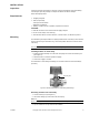
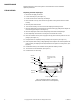
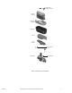
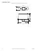


Table Of Contents
- Application
- Features
- Applicable Literature
- Inspect the package for damage. If damaged, notify the appropriate carrier immediately. If undamaged, open the package and inspect the device for obvious damage. Return damaged products.
- The MK-2690 is generally installed in an upright position. When connecting to the control air line the actuator may be swiveled to any convenient position above the center line of the valve body.
- The actuator should be removed from the valve body during valve installation.
- For information on valve linkage assembly, see General Instructions for AV-400 linkage (F-19073).
- When removing the actuator, make sure that the piston is not pulled out of the diaphragm.
- Regular maintenance of the total system is recommended to assure sustained optimum performance.
- 1. Disconnect air supply to actuator.
- 2. Loosen mounting nut. (See Figure-3.)
- 3. Lift the actuator off the valve body and linkage.
- 4. Place actuator on its top, and remove two (2) lower housing screws. Remove lower housing.
- 5. Remove piston from actuator.
- 6. Turn actuator housing over and remove the diaphragm retaining screws.
- 7. Remove diaphragm and its retainer from actuator housing by pulling them straight out from housing. (See Figure-2 and Figure-3.)
- 8. Remove diaphragm retainer from old diaphragm and install new diaphragm.
- 9. Place diaphragm and retainer in housing and secure with two screws.
- 10. Place the actuator housing on its top (open side up) and center the piston on the diaphragm. (See Figure-2.)
- 11. Pull protrusions on diaphragm through mating holes on piston. (See Figure-2.)
- 12. Push the piston down evenly, rolling diaphragm around piston. Be certain to position the piston squarely on diaphragm with equal distances from piston to housing sides. (See Figure-2.)
- 13. Install lower housing to the actuator housing with two retaining screws.
- 14. The actuator is now assembled. (See Figure-1.)
- 15. Install actuator on valve body.
- Figure-2 Positioning Piston in Diaphragm (shown with actuator in the inverted position).
- Figure-3 Exploded View of MK-2690.
- 1. Disconnect air supply to actuator.
- All dimensions in inches (millimeters in brackets). See Figure-4.

Printed in U.S.A. 1/10 © Copyright 2010 Schneider Electric All Rights Reserved. F-13893-7
Application
For proportional pneumatic control of 1/2" to 1-1/4"
VB-111 and VB-9xxx series valves.
Features
• Compact size with 6 in.
2
(39 cm
2
) effective area.
• Rugged die cast aluminum housing.
• Replaceable beaded molded neoprene diaphragm.
Applicable Literature
• Environmental Controls Cross-Reference Guide
F-23638
• Environmental Controls Reference Manual
F-21683
• Environmental Controls Application Manual
F-21335
• AV-400 Valve Linkage — General Instructions
F-19073
Pneumatic Valve Actuator
General Instructions
MK-2690