
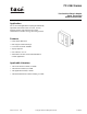
User Guide

2 © Copyright 2008 TAC All Rights Reserved. F-16290-7
Specifications
Thermostat Inputs
Setpoint Dial Range: See Table-1.
Sensing Element: Bimetal.
Differential: 2°F (1.1°C)
Thermostat Outputs
Electrical:
Switch Action, See Table-1.
Amp Ratings, See Table-2.
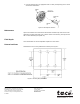
Connections: Coded screws terminals.
Environment
Ambient Temperature Limits:
Shipping & Storage, -40 to 160°F (40° to 71°C).
Operating, 40 to 140°F (4° to 60°C).
Humidity: 5 to 95% R.H., non-condensing.
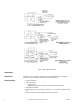
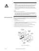
Mounting: Flush on single or 2-gang switch box or 4" x 4" (102 mm x 102 mm) surface box
or directly to wall (24 Vac only).
Location: NEMA Type 1.
Agency Listings: See Table-4.
°
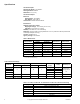
Table-1 Model Chart.
Standard Model
Dial Range
Thermometer Switch Action
Left Side Right Side
TC-1161 55° - 85°F 55° - 85°F Yes 2 SPDT
TC-1161-116 13° - 29°C 13° - 29°C Yes 2 SPDT
TC-1161-479 75° - 105°F 45° - 75°F No 2 SPDT
TC-1161-530 75° - 105°F 45° - 75°F No 2 SPDT
TC-1161-531 75° - 105°F 45° - 75°F No 2 SPDT
TC-1161-602
a
a
10°F Night depression application (24 Vac only).
55° - 85°F 55° - 85°F Yes 2 SPDT
TC-1161-770
b
b
Cover has manufacturer logo.
55° - 85°F 55° - 85°F Yes 2 SPDT
Table-2 Electrical Ratings.
Model No.
Full Load Amps Locked Rotor Amps
Current Rating
(amps)
Voltage Pilot Duty VA
24/120 Vac 240 Vac 24/120 Vac 240 Vac
TC-1161
31.5189
——
28 @ 24 Vac
140 @ 120/240
Vac
TC-1161-770 ——
TC-1161-479 ——
TC-1161-602 ——
TC-1161-530
a
— — — — 0.41 24 Vac —
TC-1161-531
a
— — — — 0.082 120 Vac —
a
3°F cooling and heating application.
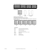
Table-3 TC-1161, TC-1161-116, TC-1161-602 & TC-1161-770 Contain the Following.
Quantity Description
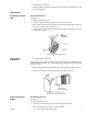
2 Blank cover inserts (left & right)
1 Cover insert with setpoint dial cutout (right)
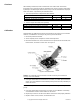
2 5/64" Allen head screws for securing cover to thermostat base
1 5/64" Allen head wrench
4 Dial stop pins to limit setpoint range
1 Thermostat