
User Guide

F-16290-7 © Copyright 2008 TAC All Rights Reserved. 5
Warning:
• Disconnect power supply before installation to prevent electrical shock and equipment
damage.
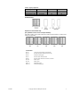
• Make all connections in accordance with the wiring diagram and in accordance with
national and local electrical codes. Class I wiring is required unless all circuits to
contacts are powered from a Class II source. Use copper conductors only.
• Do not locate the thermostat near sources of heat or cold such as lamps, motors,
sunlight, or concealed ducts or pipes, or where there is a danger of electrocution (i.e.,
shower rooms).
Caution:
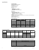
• Do not exceed ratings or the device(s).
• The thermostat is not designed for service in any location where condensation may
occur. Avoid locations where excessive moisture, corrosive fumes, or vibration is
present. NEMA Type 1 covers are intended for indoor use primarily to provide a degree
of protection against contact with the enclosed equipment.
• Thermostats with guards that restrict air flow must have heating or cooling anticipation.
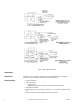
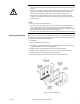
Mounting and Wiring Thermostat requires upright mounting on a flat vertical surface. Locate thermostat where it
is exposed to unrestricted circulation of air which represents the average temperature of the
controlled spaces. (See Figure-2 and Figure-7.)
1. Pull all wires.
2. Fasten mounting plate to box or wall.
3. Make electrical connection to thermostat screw type terminals. Green ground wire is
located on mounting plate for use in all applications.
4. Hook thermostat on top of mounting plate and swing down into place.
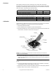
5. Remove the two (2) thermostat cover screws and remove the thermostat cover.
6. Attach thermostat to mounting plate with mounting screw.
7. Attach thermostat cover and tighten the two (2) thermostat cover screws.
Figure-2 Thermostat Mounting.