
User Guide

F-18895-6 © Copyright 2008 TAC All Rights Reserved. 3
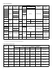
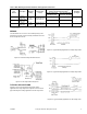
DUAL BULB SELECTION
On the dual bulb units, indoor and outdoor bulbs are
determined by the ratio selected (see Table-2). Ratio refers to
the outdoor air temperature change compared to the water
temperature change. The dial setpoint is the water
temperature setpoint when the outdoor temperature is 70°F.
To select ratio, it is necessary to know only: (1) outdoor design
temperature, (2) maximum water temperature at outdoor
design temperature, and (3) desired water temperature at
70°F outdoors. Use Table-3 to determine the required ratio
based on this information and set the dial per item (3).
Note:
If a 1-1/2:1 ratio is selected, the extra dial supplied
with the unit must be used.
Example:
Select ratio for an installation with a -10°F design
temperature and estimated supply water temperature of 75°F
at 70°F outdoors and 125°F at -10°F outdoors. From Table-3,
-10°F for 1-1/2:1 ratio, note by interpolation (70°F to 123°F
with dial at 70°F, 80°F to 133°F with dial at 80°F) that water
temperature varies from 75°F to 128°F as outdoor
temperature drops from 70°F to -10°F.
For this application, the 1-1/2:1 ratio should be selected. The
extra dial supplied with the unit would be used, and the dial set
at 75°F.
PRE-INSTALLATION
Inspection
Visually inspect the carton for damage. If damaged, notify the
appropriate carrier immediately. If undamaged, open the
carton and visually inspect the device for obvious defects.
Return damaged or defective products.
Required Installation Items
• Wiring diagram
• Tools (not provided):
Volt-ohm meter
Room temperature thermometer on °F or °C
Appropriate screwdriver(s) for cover, terminals and
mounting screws
Appropriate drill and drill bit for mounting screws
INSTALLATION
Caution:
1. Installer must be a qualified, experienced technician.
2. Disconnect power supply before installation to prevent
electrical shock and equipment damage.
3. Make all connections in accordance with the electrical
wiring diagrams, and in compliance with national and
local codes.
Use copper conductors only.
4. Do not exceed ratings of the device.
5. Avoid locations where excessive moisture, corrosive
fumes or vibrations are present.
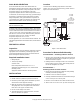
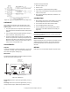
Location
Locate the device allowing proper distance to the bulb
location. The case can be mounted in any position. Refer to
Figure-2 for case dimensions.
Figure-2 Case Dimensions.
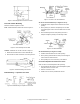
Procedure for Remote Bulb Mounting
Air Bulb Models — Mounting in Return Air Duct
1. Remove cover and provide two holes for #10 round head
screws using the housing as the template or by using the
dimensions shown in Figure-2.
2. Partially insert the mounting screws in the screw holes.
Fit the housing over the screws, slide housing down on
the screws and tighten the screws.
Air Bulb Models —
Mounting Outside of Return Air Duct
1. Prepare duct for mounting by cutting hole and providing
mounting screw holes per Figure-2.
2. Fabricate a cover as shown in Figure-3.
3. Carefully roll bulbs toward back of unit and insert through
2-1/4" x 2-1/2" (57 mm x 64 mm) hole.
4. Remove cover and attach unit to duct with #10 screws.
5. Attach cover over 2-1/4" x 2-1/2" (57 mm x 64 mm) hole.
Side
Back
Bottom
1-5/64"
2"
2-1/4"
5/16"
13-64"
1-9/16"
7/8"
1/2"
1/4"
3-5/8"
TC-4166
TC-4266
Only
7"
TC-4166
TC-4266
Only
4-5/8"
TC-4166
TC-4266
Only
Hole for 1/2" Conduit
Knockout for 3/4" Conduit
TC-4166
TC-4266
Only
Cut Hole in
Duct 2-1/4" W x
2-1/2" H for
Mounting in
Return Air
1"