
User Guide


4 © Copyright 2008 TAC All Rights Reserved. F-18895-6
Figure-3 Field Supplied Duct Hole Cover Plate.
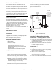
Duct and Outdoor Mounting
Maximum insertion length is 6 inches.
Duct: Install bulb with AT-208 kit as shown in Figure-4.
Figure-4 Duct Mounting with AT-208.
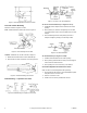
Outdoor: Install with AT-211 kit as shown in Figure-5.
1. Mount bulb to outside wall or surface with bulb clip.
2. Place shield over bulb and fasten to mounting surface.
Figure-5 Outdoor Mounting with AT-211.
Bulb Mounting — Liquid Line and Tank
Figure-6 Bulb Mounting for Liquid Line and Tank.
Figure-7 AT-201 or AT-203 Installation.
AT-201 or AT-203 Installation (see Figures-6 and 7):
1. Install bulb well or adaptor from AT-209 into 3/4" FNPT
opening.
2. Place packing nut, washers and packing from AT-209
over bulb support section and insert bulb well or AT-209
adaptor.
3. Push interlocking washers and packing into well or
adaptor and tighten packing nut until firmly sealed.
Figure-8 AT-206 Installation.
AT-206 Installation (see Figures-6 and 8):
1. Install AT-206 bulb well into 1/2" FNPT opening.
2. Place packing (included with AT-206) over bulb support
section and insert bulb into well.
3. Push packing into nut on well using a screwdriver.
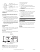
Concealed Setpoint and Lock Cover Screw
Order AT-210 concealed adjustment kit separately.
1. Peel off adhesive film from the concealed adjustment plate
and place into the recess of cover.
2. Remove screw from cover.
3. Install lock cover screw provided with AT-210.