
User Guide


F-18895-6 © Copyright 2008 TAC All Rights Reserved. 5
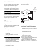
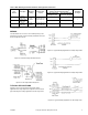
WIRING
The thermostat has one 1/2" to 3/4" conduit opening in the
bottom of the housing. Terminal coding and switch action are
shown in Figures-9 and 10.
Figure-9 Terminal Coding and Switch Action.
Figure-10 Two Stage Switch Sequence.
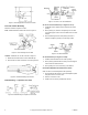
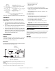
TYPICAL APPLICATIONS
Figures-11 and 12 show typical heating and cooling
applications for single stage units. Figures-13 and 14 show
typical heating and cooling applications for two stage units.
Figure-11 Typical Heating Application for Single Stage Units.
Figure-12 Typical Cooling Application for Single Stage Units.
Figure-13 Typical Heating Application for Two Stage Units.
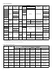
Table-4 Bulb Mounting Installation Hardware And Application Limitations.
Part
Number
Description
Mounting
Fitting
Insertion Size
in. (mm)
Application Limitations
at 250
°F (121°C) Fluid Temperature
a
Installation
per Figure
Max. Recommended
Velocity fps (m/s)
Max. Recommended
Static Press. psig (kPa)
AT-201
b
Copper
Bulb Well
3/4"
MNPT
1/2 (13) dia. O.D.
9-1/2 (241) long
11 (3.3) 250 (1728)
7
AT-203
b
Stainless Steel
Bulb Well
20 (6.1) 500 (3448)
AT-206
Copper
Bulb Well
1/2"
MNPT
1/2 (13) dia. O.D.
4-1/2 (114) long
11 (3.3) 250 (1728) 8
a
Max. recommended fluid temperature is 350 F (177°C).
b
Requires AT-209.