
User Guide


Printed in U.S.A. 8/08 © Copyright 2008 TAC All Rights Reserved. F-15571-4
DEVICE INFORMATION
Identification
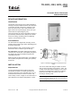
Thermostats of this family may be easily identified by
referring to the part number located on the carton and
on the back and side of the device. Stamped on the
back of the device is the date of manufacture (four
digits, the first two representing the week of the year
and the last two representing the year).
These thermostats are used for proportional control of
pneumatically activated valves, dampers and similar
devices in heating, ventilating and air conditioning
systems. See Performance table.
Pre-Installation
The thermostats are shipped with mounting screws
and three 3/4-inch long copper tubes. Wall fittings must
be ordered separately.
Before installation, make a visual inspection of the
thermostat carton for obvious signs of damage.
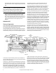
Air connections: Two plastic tubes reinforced with a
coil spring are coded M & B. The M (Black) designates
the supply main and the B (White) designates the
controlled branch line.
Model TK-1601 has three plastic tubes. The additional
tube A (White) designates the auxiliary (two-position)
branch line.
INSTALLATION
Requirements
Locate the thermostat where it will be exposed to
unrestricted circulation of air which represents the
average temperature of the controlled space. Do not
locate the thermostat near sources of heat or cold,
such as lamps, motors, sunlight, or concealed ducts or
pipes. Maximum safe ambient temperature is 150
°F.
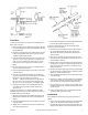
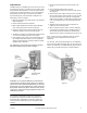
Figure-1 Mounting Thermostat to AT-507 Mortar Joint
Fitting.
The AT-507 thermostat fitting is available for either
flush or surface mounting. See Figures 1 and 3. The
AT-506 and AT-508 (wall box fittings) are for surface
mounting on all wall surfaces and flush mounting in
plastered or stud walls The AT-507 is for flush
mounting in masonry walls.
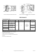
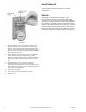
Note:
No fitting is available for use for flush mounting in
masonry walls when using the TK-1601, an electrical box is
used for this application (Figure-2).
TK-1001, 1101, 1201, 1301,
1601
Pneumatic Room Thermostats
General Instructions