
User Guide


F-15571-4 © Copyright 2008 TAC All Rights Reserved. 3
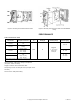
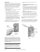
Figure-4
Procedure
To mount a thermostat on an AT-506 and AT-508 wall box
fitting, refer to Figure-3:
1. Remove and discard the cardboard cover plate on the wall
box. The cardboard cover protects the fitting while the wall
is being plastered.
2. Fasten the mounting plate to the wall box with the two flat
head screws provided. Make sure it is square with the
wall before tightening the screws.
3. If the thermostat tubing is too long for easy coiling in the
wall box, it can be cut to length. Cut the tubing at a 45°
angle, for ease in inserting the tubing into the “O” ring
seal. Be sure that the coil spring is cut flush with the
tubing.
4. Remove and discard the short piece of tubing from the
connector head of the wall box.
5. Place the fiber board insulator over the tubes on the back
of the thermostat.
6. Insert the main (black) plastic tubing into the left hand
hole in the connector head. Insert the branch line (white)
tubing in the right hand hole in the connector.
TK-1601 — Insert the auxiliary branch line (A White) in
the center hole in the connector. Insert tubes at least
1/4-inch. Do not use any lubricant on the plastic tubing.
7. Fasten the thermostat to the mounting plate with the
three Allen mounting screws provided. Tighten the
screws evenly.
To mount a thermostat on an electrical switch box. When
installing a thermostat to an electrical switch box (Figure-2) in
a masonry wall proceed as follows:
1. Attach the mounting plate to the switch box with the two
flathead screws provided. Be sure the mounting plate is
vertical.
2. Place the fiber board insulator over the tubes on the back
of the thermostat.
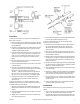
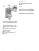
3. Slightly rotate the tubes back and forth, and push firmly
on to the fittings (Figure-5).
Figure-5
4. Fasten the thermostat to the mounting plate with the Allen
head screws provided and tighten evenly.
To mount a thermostat on an AT-507 mortar joint fitting
(Figure-1) proceed as follows:
1. Remove the screws holding the protector black in place.
Pry out and discard the protector block. Pull out and
discard the short piece of plastic tubing inserted in the
connector head.
2. Attach the thermostat mounting plate to the connector
head with the two flathead screws provided. Be sure the
mounting plate is vertical.
3. Measure 7/8-inch from the back of the thermostat and cut
the tubing at a 45° angle to make the tubing slide into the
connector head easily. Remove the coil spring from the
tubing and discard.
4. Insert two 3/4-inch lengths of copper tubing, supplied with
the thermostat into the plastic tubing to stiffen the plastic
tubing so it can be installed easily.
5. Place the fiber board insulator over the tubes on the back
of the thermostat.
6. lubricate the outside of the two plastic tubes (this applies
to the mortar joint fitting only) with water or glycerin. Be
sure that none of the lubricant gets inside the tubing.
7. Insert the tubes in to the connector head. Slightly rotate
the tubes back and forth, and push firmly into the sockets
at least 1/4 inch.
8. Fasten the thermostat to the mounting plate with Allen
screws provided, and tighten evenly.
CHECKOUT
After installing the thermostat, verify proper operation as
follows:
1. To check the nozzle and/or restriction, turn the setpoint dial
to 85°F. If the thermostat is direct acting, the output
pressure will drop. If the thermostat is reverse acting, the
output pressure will rise. Turn the setpoint dial to 55°. If the