
User Guide


4 © Copyright 2008 TAC All Rights Reserved. F-15571-4
thermostat is direct acting, the output pressure should rise.
If the thermostat is reverse acting, the output pressure will
drop.
Note:
The mount of the rise or drop in the output pressure
may vary depending on the ambient temperature in the test
area. If output is always 0 psig, the restriction may be
plugged. If output is always equal to supply or unable to
decrease below 3 psig, the nozzle may be plugged.
2. T check for active thermal element, adjust the setpoint
knob to obtain approximately 8 psig branch output.
Slightly warm the element with your hand or breath. A
direct acting thermostat will increase output pressure. A
reverse acting thermostat will decrease output pressure.
If the thermostat fails to function properly, refer to
REPAIR.
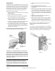
RUN/ADJUST
Theory of Operation
These thermostats are piloted relay devices incorporating an
internal pneumatic feedback principle which permits the use of
low mass bimetals and minimum leak from the
nozzle-restriction side of the circuit. This provides maximum
sensitivity with minimum air consumption. Operation may be
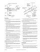
understood by referring to the schematic diagram in Figure-6.
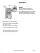
The supply air pressure (1) is channeled from the main
chamber through the restriction (2) into the nozzle (3).
The nozzle-restriction combination controls the pressure to
the pilot diaphragm of the pneumatic relay. The bimetal
positions the nozzle lever over the nozzle to regulate the
pressure to the pilot chamber. The force exerted against the
pilot diaphragm (4) actuates the relay part of the system.
The relay is operated by the pressure on the pilot diaphragm
as follows: an increase in pressure on the pilot changer
diaphragm (4) overcomes the preload force on the pilot
diaphragm spring (5), the main valve plug spring (6) and the
air pressure on the plug (7), to move the supply main valve
plus off its seat. Supply air pressure then flows into the branch
chamber (8). The resulting pressure change is transmitted to
the feedback chamber (9), where it exerts a force on the
feedback plunger (10), moving it up. The force is transmitted
to the nozzle lever through the feedback levers (11 and 12)
and spring (13) to balance the force exerted by the bimetal.
This action provides linear relationship between temperature
at the bimetal and branch line pressure.
A reduction in pressure on the pilot diaphragm allows the
diaphragm to move away from contact with the bleed valve
seat (14). The bleed valve seat then moves off the main valve
plug and allows air from the branch chamber to bleed through
the bleed valve and out to atmosphere through exhaust port
(15). This reduces the force in the feedback chamber until it is
balanced by the reduced bimetal force.
Figure-6
At that point the pilot chamber pressure is just adequate to
cause the bleed valve to seat on the main valve plug and stop
flow of air out of the branch.
Changeover: In the thermostat, two bimetals are mounted on
the bimetal bracket. On TK-1201, one bimetal is direct acting
and the other is reverse acting. On the TK-1301 and TK-1601,
both are direct acting. The bimetal which is in control of the
thermostat is determined by the position of the switchover
lever (16). The position of the switchover lever is determined
by a spring-loaded diaphragm (17), which is actuated by the
supply main pressure. When the pressure is 15 psig, the
piston is at the bottom of its stroke. At this position, the bimetal
(18) rests on the nozzle lever and the bimetal (19) is raised off
the nozzle lever by the change-over lever. when the main
pressure is changed to 20 psig, the diaphragm overcomes the
spring force and moves the piston to its upper limit, moving the
over lever to allow the bimetal (19) to rest on the nozzle lever
and lift the bimetal (18) off the nozzle lever.