
User Guide


F-15571-4 © Copyright 2008 TAC All Rights Reserved. 5
Adjustments
Throttling Range: The throttling range is set at 4F° per 10 psi
control pressure change. It should be set at the lowest value
which will allow the thermostat to control the system without
cycling under normal load conditions. The most satisfactory
setting will vary with the type of system being controlled.
If the throttling range of the thermostat as shipped is not
satisfactory, proceed as follows:
1. Measure temperature at sensing element. This should be
stable temperature.
2. Rotate setpoint dial to this temperature.
3. With 15 psig supplied to thermostat, adjust calibration
screw until 3 psig is read on branch test gauge.
4. Rotate the setpoint dial in a direction which raises the
output until 13 psig is read on the branch gauge.
5. The difference between the setpoint dial readings in Step
2 and 4 is the throttling range of the thermostat.
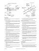
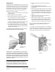
6. If the throttling range in Step 5 is not that desired, move
the throttling range slider (Figure-7) in the appropriate
direction and repeat Steps 2 through 5 until the desired
throttling range is obtained.
The calibration of the thermostat should be checked
after the throttling range has been changed.
Figure-7
Calibration: As a nominal calibration, the branch line
control pressure should be 8 psig when the setpoint is
equal to the room temperature indicated by an accurate
thermometer. On some applications, a value other than
8 psig will be required to get the desired control results.
In this case, change the 8 psig designation used in the
calibration procedure.
Caution:
The thermal element of the room thermostat is
very sensitive to temperature change. Do not affect its
temperature by touching the bimetal or breathing on the
thermostat. When calibrating the instrument, observe the
room temperature frequently and reset and setpoint dial if
required.
1. Remove the thermostat cover by loosening the cover
screw.
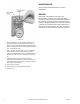
2. Using a 5/64-inch Allen wrench, unscrew
(counterclockwise rotation) the test point screw one full
turn (Figure-7).
3. Attach the test gauge rubber seal to the boss, as shown.
Using a rotary motion, push the gauge on as far as it will
go (1/4-inch minimum). See Figure-8. The tubing will
support the test gauge in a position where it will be easily
read. The supply pressure to the thermostat should be
15 psig.
4. Adjust the setpoint dial to the room temperature as
indicated on the test thermometer.
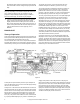
5. With a 0.48-inch six spline wrench, turn the calibration
screw (Figure-9) clockwise if the controlled pressure is
above 8 psig and counterclockwise if it below 8 psig.
Adjust the screw until the controlled pressure is 8 ±1 psi.
Note:
The hex nuts on the calibration screws are tension
devices only. They should be loosened to make an
adjustment.
The TK-1001, and TK-1101 thermostats are now calibrated.
Proceed to Step 4 below, Bimetal (18) on TK-1201, 1301 and
1601 is also calibrated. To calibrate bimetal (19) proceed as
follows using a special tool AL-80 or a small screwdriver.
Figure-8