
User Guide


Printed in U.S.A. 9/06 © Copyright 2006 TAC All Rights Reserved. F-13531-3
TAC
1354 Clifford Avenue
P. O. Box 2940
Loves Park, IL 61132-2940
www.tac.com
GENERAL INFORMATION
The pneumatic thermostats are used for proportional control
of pneumatically actuated valves, damper actuators, and
similar devices in heating ventilating and air-conditioning
systems.
The TK-5001 is a direct-acting thermostat, normally used in
heating applications. The TK-5010 is a reverse-acting
thermostat and is normally used in cooling applications.
Supply Air Pressure: 30 psig maximum; 15 psig nominal for
single acting thermostats (TK-5001 and TK-5101).
Throttling Range: Fixed-6F°, for a 10 psig branch line
pressure change, nominally 3 to 13 psig.
Air Capacity: For sizing compressors; average air
consumption is .016 standard cubic feet per minute (scfm) for
15 psig main, .024 scfm for 20 psig main. The maximum air
requirement for sizing air mains is 36 standard cubic inch per
minute (scim) for 15 psig main, 50 scim for 20 psig main.
Air Connection: One plastic tube reinforced with a coil
spring to simplify installation. Fittings are ordered separately.
A wall box and mortar joint fitting are offered. A remote in-line
restrictor is required. (see pages three and four for typical
piping.)
Locating: Locate the thermostat where it will be exposed to
unrestricted natural air circulation representative of the
average conditions of the controlled space. Do not locate
near sources on non-representative conditions (such as
lamps, motors, sunlight, radiators and concealed pipes or
ducts within the walls), which might affect the control point.
INSTALLATION
The pneumatic room thermostat fittings may be installed
either flush or surface mounted. Two types of fittings are
available: AT-506 or AT-516 (wall box fitting) for surface
mounting on all wall surfaces and flush mounting on
plastered or stud walls and the AT-519 for flush mounting on
masonry walls. The wall box fitting AT-506 or AT-516 is
installed in the wall or on the wall, attaching it firmly through
the screw holes in the back of the die cast box.
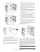
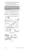
Wall Box Fitting: For installation on a wall box fitting, refer to
Figure 1 or Figure 2.
1. Remove and discard the cardboard cover plate on the wall
box (The cardboard cover protects the fitting while the wall
is being plastered).
2. Place the mounting plate against the wall. Install the two
flathead screws supplied, to hold the mounting plate to
the wall box. Before tightening the screws, align the
mounting plate so that it is square with the wall.
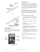
3. If the plastic tubing, attached to the thermostat, is longer
than necessary for easy coiling in the wall box, the tubing
can be cut to length. Use a side cutting or diagonal pliers,
and cut the tubing at a 45
° angle, for ease in inserting the
tubing into the “O” ring seal. Be sure that the coil spring
is left in the tubing (cut it off with the tubing).
4. Remove and discard the short plug or jumper tube which
is inserted in the connector head of the wall box, by
pulling it straight out from the hole.
5. Place the fibre board insulator over the tubing on the
back of the thermostat.
6. AT-516 - Insert the tube (white) in the center hole in the
connector.
Do not use any lubricant on the plastic tubing.
AT-506 - Using the AT-506 requires the
AT-532-111-1-01 restrictor to be located under the
thermostat cover. See Figure 2.
Insert the main plastic tubing (black) 1/4-inch or slightly
further into the hole on the left in the connector head.
Insert the branch line tubing (white) in the right hand hole
in the connector.
Do not use any lubricant on the plastic
tubing.
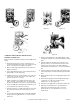
7. Fasten the thermostat to the mounting plate with the
three Allen head mounting screws provided. Tighten the
screws evenly.
8. Replace cover.
AT-517 Mortar Joint Fitting: Where the thermostat is to be
mounted on a mortar joint fitting, the following procedure is
suggested. Refer to Figure 3.
TK-5001, 5101
Pneumatic Room Thermostats
General Instructions