
User Guide


F-26004-6 Copyright 2008 TAC All Rights Reserved. 3
Note:
Although the TSMN-Series Sensors share the same base plate with the MN-Series
MicroNet™ Sensors, they are not for use with MicroNet U-Link or TAC NETWORK 8000-
Link. However, no damage will result if, by mistake, MicroNet communications are
attempted with a TSMN-Series Sensor.
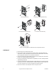
General Mounting Instructions (Screw Terminal Version)
1. Pull the system’s wires from the wall or box.
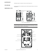
2. Pass the wires through the base plate feedthrough and fasten the base plate onto the
wall or box. Refer to Figure 2 for direct-wall mounting dimensions.
W
C A U T I O N
The Electronic Room Temperature Sensors are Class 2
only
devices and must be
connected to Class 2 wiring. Class 2 circuits must not intermix with Class 1 circuits.
3. Connect the wires to the appropriate screw terminals on the base plate. Make all
connections in accordance with the job wiring diagram and in compliance with national
and local electrical codes. Refer to Table-1 and Figure-3 for base plate terminal
identification.
4. Push any excess wire back through the base plate to minimize air flow restriction.
5. Set the electronic assembly onto the hooks on the base plate.
6. Secure the electronic assembly to the base plate by tightening all screws.
Note:
Start all screws one to two turns before tightening.
7. Install the cover by engaging the bottom tabs first and snapping the top end into place.
Note that the top end of the cover is identified on its back surface.
Note:
To remove the sensor cover, once installed, simultaneously press the middle of the
sensor with your thumb and pull firmly on the top edge of the cover with your fingers.
General Mounting Instructions (Pigtail Lead Version)
1. Pull the system’s wires from the wall or box.
2. Attach the system’s wires from the wall to the pigtails from the TSMN unit. These leads
are not polarity sensitive. Make all connections in accordance with the job wiring
diagram and in compliance with national and local electrical codes.
Note:
The pigtail leads from the TSMN unit should not have excessive stress applied when
connected to the system’s wires.
W
C A U T I O N
The Electronic Room Temperature Sensors are Class 2
only
devices and must be con-
nected to Class 2 wiring. Class 2 circuits must not intermix with Class 1 circuits.
3. Fasten the base plate onto the wall or box. Refer to Figure-2 for mounting dimensions.
4. Set the faceplate assembly onto the hooks on the base plate.
5. Secure the faceplate assembly to the base plate by tilting the assembly down, locking
it under the latching tab. Pull up slightly on the assembly to ensure it is secure.
6. Install the cover by engaging the bottom tabs first and snapping the top end into place.
Note that the top end of the cover is identified on its back surface.
Note:
To remove the sensor cover, once installed, simultaneously press the middle of the
sensor with your thumb and pull firmly on the top edge of the cover with your fingers.