
User Guide


4 Copyright 2008 TAC All Rights Reserved. F-26004-6
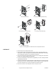
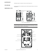
Figure-1 Mounting Options for Electronic Room Temperature Sensor.
CHECKOUT
1. Remove wires from the temperature sensor.
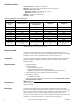
2. Using a DVM, measure the appropriate resistance between terminals SPACE and
COM. Refer to Table-1 and Figure-3 for base plate terminal identification and Table-2
for the appropriate resistance for the unit being checked out.
3. Press the override button (if applicable) and observe meter reading. When the button is
pressed, the reading should be less than 200
Ω.
4. Connect the DVM between COM and SP+ (if applicable). The meter reading should be
approximately 1100 ohms.
5. Connect the DVM between COM and SETPT (if applicable) and move the temperature
setpoint knob. The meter reading should be no less than 2500
Ω (11,000Ω is typical), at
the scale end points and no more than 29,000
Ω at the mid scale point.
6. Reconnect the wires to the temperature sensor and replace cover.
2 X 4 Electrical Box Mounting.
1/4 DIN Electrical Box Mounting.
2 X 4 Electrical Box Pigtail Mounting.
Surface Box Mountin
g
.
Direct-Wall Mounting.