
Product Overview
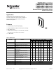
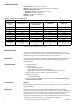
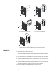
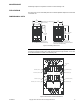
Table Of Contents
- Application
- Features
- SPECIFICATIONS
- Sensing Element:
- Mounting:
- Ambient Temperature Limits:
- Humidity:
- Locations:
- Table-2 Temperature Versus Resistance.
- INSTALLATION
- Note: Although the TSMN-Series Sensors share the same base plate with the MN-Series MicroNet™ Sensors, they are not for use with...
- General Mounting Instructions (Screw Terminal Version)
- 1. Pull the system’s wires from the wall or box.
- 2. Pass the wires through the base plate feedthrough and fasten the base plate onto the wall or box. Refer to Figure 2 for direct-wall mounting dimensions.
- 3. Connect the wires to the appropriate screw terminals on the base plate. Make all connections in accordance with the job wirin...
- 4. Push any excess wire back through the base plate to minimize air flow restriction.
- 5. Set the electronic assembly onto the hooks on the base plate.
- 6. Secure the electronic assembly to the base plate by tightening all screws.
- 1. Pull the system’s wires from the wall or box.
- General Mounting Instructions (Screw Terminal Version)
- Note: Start all screws one to two turns before tightening.
- Note: To remove the sensor cover, once installed, simultaneously press the middle of the sensor with your thumb and pull firmly on the top edge of the cover with your fingers.
- Note: The pigtail leads from the TSMN unit should not have excessive stress applied when connected to the system’s wires.
- 3. Fasten the base plate onto the wall or box. Refer to Figure-2 for mounting dimensions.
- 4. Set the faceplate assembly onto the hooks on the base plate.
- 5. Secure the faceplate assembly to the base plate by tilting the assembly down, locking it under the latching tab. Pull up slightly on the assembly to ensure it is secure.
- 6. Install the cover by engaging the bottom tabs first and snapping the top end into place. Note that the top end of the cover is identified on its back surface.
- Note: To remove the sensor cover, once installed, simultaneously press the middle of the sensor with your thumb and pull firmly on the top edge of the cover with your fingers.
- Figure-1 Mounting Options for Electronic Room Temperature Sensor.
- CHECKOUT
- 1. Remove wires from the temperature sensor.
- 2. Using a DVM, measure the appropriate resistance between terminals SPACE and COM. Refer to Table-1 and Figure-3 for base plate terminal identification and Table-2 for the appropriate resistance for the unit being checked out.
- 3. Press the override button (if applicable) and observe meter reading. When the button is pressed, the reading should be less than 200W.
- 4. Connect the DVM between COM and SP+ (if applicable). The meter reading should be approximately 1100 ohms.
- 5. Connect the DVM between COM and SETPT (if applicable) and move the temperature setpoint knob. The meter reading should be no less than 2500W (11,000W is typical), at the scale end points and no more than 29,000W at the mid scale point.
- 6. Reconnect the wires to the temperature sensor and replace cover.
- 1. Remove wires from the temperature sensor.
- MAINTENANCE
- FIELD REPAIR
- DIMENSIONAL DATA
- Note: The rating label on the base plate covers an additional mounting hole. If it is necessary to use this mounting hole, simply press the screw through the label. A cross hair on the label identifies the location of the mounting hole.

2 Copyright 2009 Schneider Electric All Rights Reserved. F-26004-7
SPECIFICATIONS
Sensing Element: See Table-1 and Table-2.
Mounting: Direct-wall, 2 x 4 electrical box, 1/4 DIN, or surface box.
Ambient Temperature Limits:
Shipping & Storage, -40 to 160 °F (-40 to 71 °C)
Operating, 40 to 140 °F (4 to 60 °C)
Humidity: 5 to 95%, non-condensing.
Locations: NEMA.
Table-2 Temperature Versus Resistance.
*TSMN-90110 does not have a shunt resistor.
INSTALLATION
The electronic room temperature sensor is packaged, in disassembled form, in one
container. It consists of three major parts: a pre-wirable base plate; an electronic assembly
containing the sensor and its associated circuitry; and a removable cover.
Inspection Inspect the package for damage. If damaged, notify the appropriate carrier immediately. If
undamaged, open the package and inspect the device for obvious damage. Return
damaged products.
Requirements • Job wiring diagrams
• Tools (not provided):
– Digital volt-ohm meter (DVM)
– Appropriate drill and drill bit for mounting screws
– Appropriate screwdrivers for mounting screws and terminal connections
• Training: Installer must be a qualified, experienced technician
• Appropriate accessories
– Communication adapter
• For use of this product with TAC System 8000, refer to the Environmental Controls
Application Manual, F-21335
Precautions Warning
Electrical shock hazard! Disconnect power before installation to prevent electrical shock or
equipment damage.
Mounting Locate the sensor where it will be exposed to an unrestricted circulation of air which
represents the average temperature of the controlled space. Do not locate the sensor near
sources of heat or cold such as lamps, motors, sunlight, or concealed ducts or pipes. The
sensor is designed for service in any normally encountered human environment.
The electronic room temperature sensor may be installed directly onto a wall, or onto a 2 X 4
electrical box, a 1/4 DIN electrical box, or a surface box. Refer to Figure 1.
Nominal Resistance Value
Temperature
°F (°C)
TSMN-90110 Series
Ω
TSMN-90xxx-85x Series
TSMN-57011-850
Ω
TSMN-58011
Ω
TSMN-81011
Ω
40 (4) — 7596 1017 935.9
50 (10) 18790 6938 1039 956.9
68 (20) 12260 5798 1077.9 995.6
77 (25) 10000 5238 1097.3 1015.4
86 (30) 8194 4696 1116.7 1035.4
104 (40) 5592 3707 1155.4 1076.2
122 (50) 3893 2875 1194 1118.0
140 (60) 2760 2206 1232.4 1160.9
Sensor Type
Thermistor, 10ΩK at 77
°F
(25
°C)
Thermistor, 10ΩK at 77
°F
(25
°C), *with 11ΩK shunt
resistor
Platinum, 1000 Ω at 32
°F
(0
°C)
Balco, 1000 Ω at 70
°F
(21.1
°C)