
Product Overview
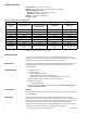
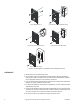
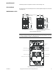
Table Of Contents
- Application
- Features
- SPECIFICATIONS
- Sensing Element:
- Mounting:
- Ambient Temperature Limits:
- Humidity:
- Locations:
- Table-2 Temperature Versus Resistance.
- INSTALLATION
- Note: Although the TSMN-Series Sensors share the same base plate with the MN-Series MicroNet™ Sensors, they are not for use with...
- General Mounting Instructions (Screw Terminal Version)
- 1. Pull the system’s wires from the wall or box.
- 2. Pass the wires through the base plate feedthrough and fasten the base plate onto the wall or box. Refer to Figure 2 for direct-wall mounting dimensions.
- 3. Connect the wires to the appropriate screw terminals on the base plate. Make all connections in accordance with the job wirin...
- 4. Push any excess wire back through the base plate to minimize air flow restriction.
- 5. Set the electronic assembly onto the hooks on the base plate.
- 6. Secure the electronic assembly to the base plate by tightening all screws.
- 1. Pull the system’s wires from the wall or box.
- General Mounting Instructions (Screw Terminal Version)
- Note: Start all screws one to two turns before tightening.
- Note: To remove the sensor cover, once installed, simultaneously press the middle of the sensor with your thumb and pull firmly on the top edge of the cover with your fingers.
- Note: The pigtail leads from the TSMN unit should not have excessive stress applied when connected to the system’s wires.
- 3. Fasten the base plate onto the wall or box. Refer to Figure-2 for mounting dimensions.
- 4. Set the faceplate assembly onto the hooks on the base plate.
- 5. Secure the faceplate assembly to the base plate by tilting the assembly down, locking it under the latching tab. Pull up slightly on the assembly to ensure it is secure.
- 6. Install the cover by engaging the bottom tabs first and snapping the top end into place. Note that the top end of the cover is identified on its back surface.
- Note: To remove the sensor cover, once installed, simultaneously press the middle of the sensor with your thumb and pull firmly on the top edge of the cover with your fingers.
- Figure-1 Mounting Options for Electronic Room Temperature Sensor.
- CHECKOUT
- 1. Remove wires from the temperature sensor.
- 2. Using a DVM, measure the appropriate resistance between terminals SPACE and COM. Refer to Table-1 and Figure-3 for base plate terminal identification and Table-2 for the appropriate resistance for the unit being checked out.
- 3. Press the override button (if applicable) and observe meter reading. When the button is pressed, the reading should be less than 200W.
- 4. Connect the DVM between COM and SP+ (if applicable). The meter reading should be approximately 1100 ohms.
- 5. Connect the DVM between COM and SETPT (if applicable) and move the temperature setpoint knob. The meter reading should be no less than 2500W (11,000W is typical), at the scale end points and no more than 29,000W at the mid scale point.
- 6. Reconnect the wires to the temperature sensor and replace cover.
- 1. Remove wires from the temperature sensor.
- MAINTENANCE
- FIELD REPAIR
- DIMENSIONAL DATA
- Note: The rating label on the base plate covers an additional mounting hole. If it is necessary to use this mounting hole, simply press the screw through the label. A cross hair on the label identifies the location of the mounting hole.

4 Copyright 2009 Schneider Electric All Rights Reserved. F-26004-7
Figure-1 Mounting Options for Electronic Room Temperature Sensor.
CHECKOUT
1. Remove wires from the temperature sensor.
2. Using a DVM, measure the appropriate resistance between terminals SPACE and
COM. Refer to Table-1 and Figure-3 for base plate terminal identification and Table-2
for the appropriate resistance for the unit being checked out.
3. Press the override button (if applicable) and observe meter reading. When the button is
pressed, the reading should be less than 200
Ω.
4. Connect the DVM between COM and SP+ (if applicable). The meter reading should be
approximately 1100 ohms.
5. Connect the DVM between COM and SETPT (if applicable) and move the temperature
setpoint knob. The meter reading should be no less than 2500
Ω (11,000Ω is typical), at
the scale end points and no more than 29,000Ω at the mid scale point.
6. Reconnect the wires to the temperature sensor and replace cover.
2 X 4 Electrical Box Mounting.
1/4 DIN Electrical Box Mounting.
2 X 4 Electrical Box Pigtail Mounting.
Surface Box Mounting.
Direct-Wall Mounting.