
User Guide

F-26075-2 © Copyright 2008 TAC All Rights Reserved. 7
Cavitation Limitations
on Valve Pressure
Drop
A valve selected with too high a pressure drop can cause erosion of discs and/or wire
drawing of the seat. In addition, cavitation can cause noise, damage to the valve trim (and
possibly the body), and choke the flow through the valve.
Do not exceed the maximum differential pressure (pressure drop) for the valve selected.
The following formula can be used on higher temperature water systems, where cavitation
could be a problem, to estimate the maximum allowable pressure drop across the valve:
Pm = 0.5 (P
1
– Pv)
Where:
Pm = Maximum allowable pressure drop (psi)
P
1
= Absolute inlet pressure (psia)
Pv = Absolute vapor pressure (psia) (refer to Table-6 or Table-7)
Note:
Add 14.7 psi to gauge supply pressure to obtain absolute pressure value.
For example, if a valve is controlling 200°F water at an inlet pressure of 18 psig, the
maximum pressure drop allowable would be:
Pm = 0.5 [(18 + 14.7) – 11.53] = 10.6 psi
(Vapor pressure of 200°F water is 11.53 psia.)
If the pressure drop for this valve is less than 10.6 psi, cavitation should not be a problem.
Systems where cavitation is shown to be a problem can sometimes be redesigned to provide
lower inlet velocities. Valves having harder seat materials should be furnished if inlet
velocities cannot be lowered.
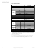
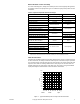
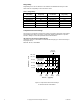
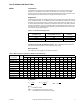
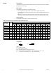
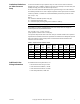
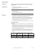
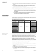
Table-7 Vapor Pressure of Water Table.
Additional Valve
Sizing Information
For additional valve sizing information, see:
• CA-28 Control Valve Sizing, F-13755
• Valve Selection Chart Water, F-11080
• Valve Selection Chart Steam, F-11366
• Valve Sizing Slide Rule, TOOL-150
Water
Temp.
(°F)
Vapor
Pressure
(psia)
Water
Temp.
(°F)
Vapor
Pressure
(psia)
Water
Temp.
(°F)
Vapor
Pressure
(psia)
Water
Temp.
(°F)
Vapor
Pressure
(psia)
40 0.12 90 0.70 140 2.89 190 9.34
50 0.18 100 0.95 150 3.72 200 11.53
60 0.26 110 1.28 160 4.74 210 14.12
70 0.36 120 1.69 170 5.99 220 17.19
80 0.51 130 2.22 180 7.51 230 20.78