
User Guide

8 © Copyright 2008 TAC All Rights Reserved. F-26075-2
INSTALLATION
Inspection Inspect the package for damage. If damaged, notify the appropriate carrier immediately.
If undamaged, open the package and inspect the device for obvious damage. Return
damaged products.
Requirements • Tools (not provided): Pipe wrenches
• Training: Installer must be a qualified, experienced technician
• Appropriate accessories
Caution:
• Install the valve with the flow in the direction of the flow arrow (“A” port is the inlet and
“AB” port is the outlet).
• Do not exceed the ratings of the device.
• Avoid locations where excessive moisture, corrosive fumes, or vibration are present.
Mounting 1. The valve should be mounted in a weather-protected area in a location that is within the
ambient limits of the actuator. When selecting a location, allow sufficient room for valve
linkage, actuator, and other accessories and for service of the product.
2. The preferred mounting position for the valve is with the valve stem vertical above the
valve body. Avoid mounting the valve so that the valve stem is below horizontal.
3. On steam applications where the ambient temperature approaches the limit of the
actuator, the valve stem should be mounted 45° from vertical.
4. The valves must be piped with the “A” port as the inlet and the “AB” port as the outlet.
Screwed Valve Bodies
The VB-7213-0-4 series screwed valve bodies conform to American Standard Taper Pipe
Threads (NPT).
1. Apply pipe dope sparingly to all but the last two threads of a properly threaded, reamed,
and cleaned pipe. Make sure that pipe chips, scale, etc. do not get into the pipe since this
material may lodge in the valve seat and prevent proper closing and opening of the valve.
2. Start the joint by hand screwing the pipe into the valve. If the thread engagement feels
“right,” turn the pipe by hand as far as it will go.
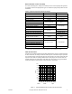
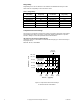
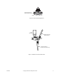
3. Use a pipe wrench to fully tighten the valve to the pipe. Do not over tighten or strip
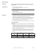
threads. See Table-8 and Figure-3 for the normal engagement length of the threads.
Figure-4 shows a means of tightening the pipe so that the valve is not twisted or
crushed.
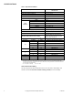
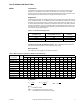
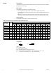
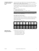
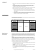
Table-8 Normal Thread Engagement Between Male Pipe Thread and Valve Body.
Valve Size Inches
(NPT)
Normal Engagement
Valve Size Inches
(NPT)
Normal Engagement
1/2" 1/2" 1-1/4" 11/16"
3/4" 9/16" 1-1/2" 11/16"
1" 11/16" 2" 3/4"