
User Guide


Copyright 2010, Schneider Electric
All brand names, trademarks and registered
trademarks are the property of their respective
owners. Information contained within this
document is subject to change without notice.
F-27194-5
www.schneider-electric.com/buildings
Schneider Electric
1354 Clifford Avenue
P.O. Box 2940
Loves Park, IL 61132-2940
On October 1st, 2009, TAC became the Buildings business of its parent company Schneider Electric. This document reflects the visual identity of Schneider Electric,
however there remains references to TAC as a corporate brand in the body copy. As each document is updated, the body copy will be changed to reflect appropriate
cor
p
orate brand chan
g
es.
A
C
D
B
E
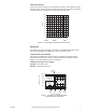
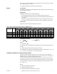
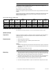
Figure-6 Flange Dimensions
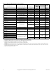
Table-9 Flange Detail for American Standard 125 psi Cast Iron Pipe Flanges (Figure-6)
Nominal Pipe
Size
Flanges Drilling Bolting
Length of
Machine Bolts
E
Flange
Diameter
A
Flange
Thickness
B
Diameter of
Bolt Circle
C
Diameter of
Bolt Holes
D
Number of
Bolts
Diameter of
Bolts
2-1/2” 7” 11/16” 5-1/2”
3/4”
4
5/8”
2-1/2”
3” 7-1/2” 3/4” 6”
4” 9”
15/16”
7-1/2”
8
3"
5" 10" 8-1/2"
7/8" 3/4"
6" 11" 1" 9-1/2" 3-1/4"