
User Guide

6 © Copyright 2010 Schneider Electric All Rights Reserved. F-27194-5
VALVE SIZING AND SELECTION
Water Flow Coefficient (C
v
)
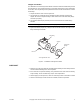
Sizing a valve requires selecting a flow coefficient (C
v
), which is defined as the flow rate in
gallons per minute (gpm) of 60°F water that will pass through the fully open valve with a 1
psi pressure drop (
Δp). It is calculated according to the formulas shown in C
v
Equation for
Water and C
v
Equation for Steam.
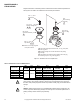
Since the flow rate through the heat exchanger is usually specified, the only variable
normally available in sizing a valve is the pressure drop. The following information can be
used to determine what pressure drop to use in calculating a valve C
v
. Using the calculated
C
v
, consult Table-4 or Table-5 to select the valve body with the nearest available C
v
.
Caution: Be sure that the anticipated pressure drop across the valve will not exceed the
close-off pressure rating and the maximum pressure differential rating listed in the Vx-8xxx
Selection Guide, F-27199.
Two-position
Two-position control valves are normally selected “line size” to keep pressure drop at a
minimum. If it is desirable to reduce the valve below line size, then 10% of “available
pressure” (that is, the pump pressure differential available between supply and return mains
with design flow at the valve location) is normally used to select the valve.
Proportional
Proportional control valves are usually selected to take a pressure drop equal to at least 50%
of the “available pressure.” As “available pressure” is often difficult to calculate, the normal
procedure is to select the valve using a pressure drop at least equal to the drop in the coil
or other load being controlled (except where small booster pumps are used) with a minimum
recommended pressure drop of 5 psi (34 kPa). When the design temperature drop is less
than 60°F (33°C) for conventional heating systems, higher pressure drops across the valve
are needed for good results (Table-3).
Secondary Circuits with Small Booster Pumps: 50% of available pressure difference
(equal to the drop through load, or 50% of booster pump head).
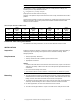
Water Table
See Table-4 for water capacity of VB-8223 series valves.
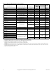
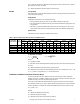
C
v
Equation for Water
Where:
C
v
= Coefficient of flow.
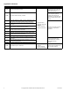
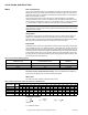
Table-3 Conventional Heating System
Design Temperature
Load Drop °F (°C)
Recommended Pressure Drop
a
(% of Available Pressure)
a
Recommended minimum pressure drop = 5 psi (34 kPa).
Multiplier on
Load Drop
60 (33) or More 50% 1 x Load Drop
40 (22) 66% 2 x Load Drop
20 (11) 75% 3 x Load Drop
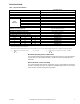
Table-4 Water Capacity in Gallons Per Minute for VB-8223 Series
Valve Body
Part Number
C
v
Rating
Differential Pressure (
ΔP in psi)
123456789101520253035
VB-8223-0-5-12 56 56 79 97 112 125 137 148 158 168 177 217 250 280 307 331
VB-8223-0-5-13 85 85 120 147 170 190 208 225 240 255 269 329 380 425 466 503
VB-8223-0-5-14 145 145 205 251 290 324 355 384 410 435 459 562 648 725 794 858
VB-8223-0-5-15 240 240 339 416 480 537 588 635 679 720 759 930 1073 1200 1315 1420
VB-8223-0-5-16 370 370 523 641 740 827 906 979 1047 1110 1170 1433 1655 1850 2027 2189
C
v
gpm
PΔ
-----------=
ΔP
gpm
C
v
------------
⎝⎠
⎛⎞
2
=
gpm C
v
PΔ=