
User Guide

8 © Copyright 2010 Schneider Electric All Rights Reserved. F-27194-5
Note: Add 14.7 psi to the gauge supply pressure to obtain the absolute pressure value.
For example, if a valve is controlling 200°F water at an inlet pressure of 18 psig, the
maximum pressure drop allowable would be:
P
m
= 0.5 [(18 + 14.7) – 11.53] = 10.6 psi
(Vapor pressure of 200°F water is 11.53 psi.)
Therefore, if the pressure drop for this valve is less than 10.6 psi, cavitation should not be a
problem.
Systems where cavitation is shown to be a problem can sometimes be redesigned to provide
lower inlet velocities. Valves having harder seat materials should be furnished if inlet
velocities cannot be lowered.
Additional Valve Sizing Information
For additional valve sizing information, see the Vx-8xxx Selection Guide, F-27199.
INSTALLATION
Inspection Inspect the package for damage. If damaged, notify the appropriate carrier immediately. If
undamaged, open the package and inspect the device for obvious damage. Return
damaged products.
Requirements • Tools (not provided): Wrenches.
• Training: Installer must be a qualified, experienced technician
• Appropriate accessories
Caution:
• Install the valve with the flow in the direction of the flow arrow (“A” port is the inlet and
“AB” port is the outlet). A label on the side of the valve provides port identification and
a flow arrow.
• Do not exceed the ratings of the device.
• Avoid locations where excessive moisture, corrosive fumes, or vibration are present.
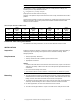
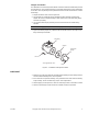
Mounting 1. The valve should be mounted in a weather-protected area in a location that is within the
ambient limits of the actuator. When selecting a location, allow sufficient room for valve
linkage, actuator, and other accessories and for service of the product.
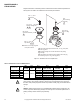
2. The preferred mounting position for the valve is with the valve stem vertical above the
valve body. Avoid mounting the valve so that the valve stem is below horizontal.
3. On steam applications, the valve stem should be 45° from vertical.
4. The valve must be piped with the “A” port as the inlet and the “AB” port as the outlet.
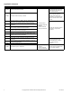
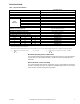
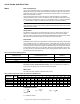
Table-6 Vapor Pressure of Water Table
Water Temp.
(°F)
Vapor
Pressure
(psia)
Water Temp.
(°F)
Vapor
Pressure
(psia)
Water Temp.
(°F)
Vapor
Pressure
(psia)
Water Temp.
(°F)
Vapor
Pressure
(psia)
40 0.12 90 0.70 140 2.89 190 9.34
50 0.18 100 0.95 150 3.72 200 11.53
60 0.26 110 1.28 160 4.74 210 14.12
70 0.36 120 1.69 170 5.99 220 17.19
80 0.51 130 2.22 180 7.51 230 20.78