
User Guide

F-27194-5 © Copyright 2010 Schneider Electric All Rights Reserved. 9
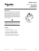
Flanged Valve Bodies
The VB-8223-0-5-P series flanged valve bodies conform to American Standard 125 psi Cast
Iron Pipe Flanges. The companion flanges (not provided) should be the same specification
as the valve. The 125 psi flanges have plain flat faces and should not be bolted to a raised
faced flange.
1. All parts should be clean to assure tight seals.
2. The pipe with the companion flanges installed should be properly supported and
aligned. Be sure the companion flange is flush with the face of the valve body flange
and lined up squarely.
3. Use a gasket material (not provided) that is recommended for the medium being
handled.
Caution: Do not apply pipe dope to the valve flange, gasket, or companion flange.
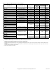
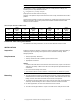
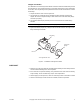
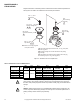
4. Figure-3 shows the proper way a flanged valve should be mounted. See Figure-6 for
flange and flange bolt details.
CHECKOUT
1. Make sure the valve stem operates smoothly before installing the valve linkage and the
actuator. Initial breakaway force can be expected.
2. If the stem does not operate smoothly, it may indicate that the valve stem was bent by
rough handling. These conditions may require valve replacement.
3. After the piping is under pressure, check the valve body and the connections for leaks.
4. After the valve linkage and the actuator are installed, check their operation.
Valve Body
Gasket*
Com
p
anio
n
Flan
g
e
*
*Not su
pp
lied with valve
.
Bolt *
Nut *
Figure-3 Installation of Flanged End Valves