
User Guide
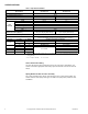
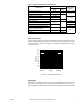
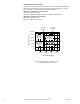
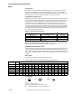
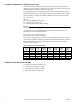
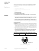
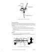
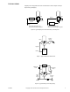
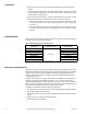
Table Of Contents
- Application
- Features
- Applicable Literature
- SPECIFICATIONS
- VALVE SIZING AND SELECTION
- Water
- Cavitation Limitations on Valve Pressure Drop
- Additional Valve Sizing Information
- INSTALLATION
- Inspection
- Requirements
- Mounting
- 1. The valve should be mounted in a weather-protected area in a location that is within the ambient limits of the actuator. When...
- 1. Apply pipe dope sparingly to all but the last two threads of a properly threaded, reamed, and cleaned pipe. Make sure that pi...
- Table-6 Normal Thread Engagement Between Male Pipe Thread and Valve Body.
- Figure-3 Normal Thread Engagement.
- Figure-4 Installation of Screwed End Valves.
- 1. All parts should be clean to assure the best results.
- 2. The pipe with the companion flanges installed should be properly supported and aligned. Be sure the companion flange is flush with the face of the valve body flange and lined up squarely.
- 3. Use a gasket material (not provided) that is recommended for the medium being handled.
- 4. See Figure-5 for flange and flange bolt details. Figure-5 also shows the proper way a flanged valve should be mounted.
- Figure-5 Installation of Flanged End Valves.
- TYPICAL PIPING
- CHECKOUT
- 1. Make sure the valve stem operates freely before installing the valve linkage and the actuator.
- 2. If the stem does not operate freely, it may indicate that the valve was twisted or crushed during installation or that the stem was bent by rough handling. These conditions may require that the valve be replaced.
- 3. After the piping is under pressure, check the valve body and the connections for leaks.
- 4. After the valve linkage and the actuator are installed, check their operation.
- a. Drive the actuator and run the valve to the stem down position. Make sure the linkage and valve stem move freely. At the stem down position, the valve should shut off the “B” port.
- b. Drive the actuator and valve to the stem up position. Again, the valve stem and linkage should operate smoothly. At the stem up position, the valve should shut off the “A” port.
- 1. Make sure the valve stem operates freely before installing the valve linkage and the actuator.
- MAINTENANCE
- Water System Maintenance
- DIMENSIONAL DATA

10 © Copyright 2010 Schneider Electric All Rights Reserved. F-24393-3
CHECKOUT
1. Make sure the valve stem operates freely before installing the valve linkage and the
actuator.
2. If the stem does not operate freely, it may indicate that the valve was twisted or crushed
during installation or that the stem was bent by rough handling. These conditions may
require that the valve be replaced.
3. After the piping is under pressure, check the valve body and the connections for leaks.
4. After the valve linkage and the actuator are installed, check their operation.
a. Drive the actuator and run the valve to the stem down position. Make sure the link-
age and valve stem move freely. At the stem down position, the valve should shut off
the “B” port.
b. Drive the actuator and valve to the stem up position. Again, the valve stem and link-
age should operate smoothly. At the stem up position, the valve should shut off the
“A” port.
MAINTENANCE
Regular maintenance of the total system is recommended to assure sustained performance.
See Table-7 for maintenance kit part numbers.
*Kit includes replacement packing and stem & plug assembly.
Water System Maintenance
All heating and cooling systems are susceptible to valve and system problems caused by
improper water treatment and system storage procedures. These guidelines are provided to
help avoid valve and water system problems resulting from improperly treated water or
storage procedures in cooling and hot water systems, and to obtain maximum life from
Schneider Electric valves.
Durability of valve stems and packings is dependent on maintaining non-damaging water
conditions. Inadequate water treatment or filtration, not in accordance with chemical
supplier/ASHRAE handbook recommendations, can result in corrosion, scale, and abrasive
particle formation. Scale and particulates can result in stem and packing scratches and can
adversely affect packing life and other parts of the hydronic system.
To maintain non-damaging conditions, follow these guidelines:
• Clean the system prior to start up. Use a nitrite or molybdate-based treatment program.
• Use filtration equipment where needed.
• Properly store off-line systems and monitor water treatment results using corrosion test
coupons.
• Follow the advice of a water treatment professional.
• Consult EN-205 for further details.
Table-7 Maintenance Kits for VB-9313 Valves.
Valve Body
Part Number
Replacement
Packing Assembly
Valve Repair Kit*
VB-9313-0-4-12
YBA-651-1
RYB-931-12
VB-9313-0-4-13 RYB-931-13
VB-9313-0-5-12 RYB-931-12
VB-9313-0-5-13 RYB-931-13
VB-9313-0-5-14 RYB-931-14
VB-9313-0-5-15 RYB-931-15
VB-9313-0-5-16 RYB-931-16