
User Guide
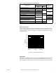
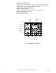
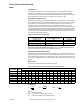
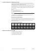
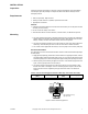
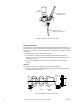
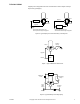
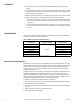


Table Of Contents
- Application
- Features
- Applicable Literature
- SPECIFICATIONS
- VALVE SIZING AND SELECTION
- Water
- Cavitation Limitations on Valve Pressure Drop
- Additional Valve Sizing Information
- INSTALLATION
- Inspection
- Requirements
- Mounting
- 1. The valve should be mounted in a weather-protected area in a location that is within the ambient limits of the actuator. When...
- 1. Apply pipe dope sparingly to all but the last two threads of a properly threaded, reamed, and cleaned pipe. Make sure that pi...
- Table-6 Normal Thread Engagement Between Male Pipe Thread and Valve Body.
- Figure-3 Normal Thread Engagement.
- Figure-4 Installation of Screwed End Valves.
- 1. All parts should be clean to assure the best results.
- 2. The pipe with the companion flanges installed should be properly supported and aligned. Be sure the companion flange is flush with the face of the valve body flange and lined up squarely.
- 3. Use a gasket material (not provided) that is recommended for the medium being handled.
- 4. See Figure-5 for flange and flange bolt details. Figure-5 also shows the proper way a flanged valve should be mounted.
- Figure-5 Installation of Flanged End Valves.
- TYPICAL PIPING
- CHECKOUT
- 1. Make sure the valve stem operates freely before installing the valve linkage and the actuator.
- 2. If the stem does not operate freely, it may indicate that the valve was twisted or crushed during installation or that the stem was bent by rough handling. These conditions may require that the valve be replaced.
- 3. After the piping is under pressure, check the valve body and the connections for leaks.
- 4. After the valve linkage and the actuator are installed, check their operation.
- a. Drive the actuator and run the valve to the stem down position. Make sure the linkage and valve stem move freely. At the stem down position, the valve should shut off the “B” port.
- b. Drive the actuator and valve to the stem up position. Again, the valve stem and linkage should operate smoothly. At the stem up position, the valve should shut off the “A” port.
- 1. Make sure the valve stem operates freely before installing the valve linkage and the actuator.
- MAINTENANCE
- Water System Maintenance
- DIMENSIONAL DATA

Copyright 2010, Schneider Electric
All brand names, trademarks and registered
trademarks are the property of their respective
owners. Information contained within this
document is subject to change without notice.
F-24393-3
www.schneider-electric.com/buildings
Schneider Electric
1354 Clifford Avenue
P.O. Box 2940
Loves Park, IL 61132-2940
On October 1st, 2009, TAC became the Buildings business of its parent company Schneider Electric. This document reflects the visual identity of Schneider El ectric,
however there remains references to TAC as a corporate brand in the body copy. As each document is updated, the body copy will be changed to reflect appropriate
cor
p
orate brand chan
g
es.
Table-9 Flange Detail for American Standard 125 lb. Cast Iron Pipe Flanges.
(Figure-11).
Nominal
Pipe Size
Flanges Drilling Bolting
Length of
Machine
Bolts
E
Flange
Diameter
A
Flange
Thickness
B
Diameter
of Bolt
Circle
C
Diameter
of Bolt
Holes
D
Number
of Bolts
Diameter
of Bolts
2-1/2" 7" 11/16" 5-1/2"
3/4"
4
5/8"
2-1/2"
3" 7-1/2" 3/4" 6"
4" 9"
15/16"
7-1/2"
8
3"
5" 10" 8-1/2"
7/8" 3/4"
6" 11" 1" 9-1/2" 3-1/4"
Figure-11 Flange Dimensions.
E
D
C
A
B