
User Guide
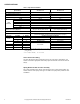
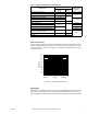
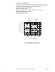
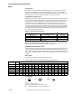
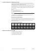
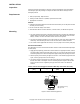
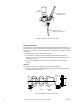
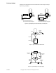
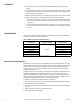
Table Of Contents
- Application
- Features
- Applicable Literature
- SPECIFICATIONS
- VALVE SIZING AND SELECTION
- Water
- Cavitation Limitations on Valve Pressure Drop
- Additional Valve Sizing Information
- INSTALLATION
- Inspection
- Requirements
- Mounting
- 1. The valve should be mounted in a weather-protected area in a location that is within the ambient limits of the actuator. When...
- 1. Apply pipe dope sparingly to all but the last two threads of a properly threaded, reamed, and cleaned pipe. Make sure that pi...
- Table-6 Normal Thread Engagement Between Male Pipe Thread and Valve Body.
- Figure-3 Normal Thread Engagement.
- Figure-4 Installation of Screwed End Valves.
- 1. All parts should be clean to assure the best results.
- 2. The pipe with the companion flanges installed should be properly supported and aligned. Be sure the companion flange is flush with the face of the valve body flange and lined up squarely.
- 3. Use a gasket material (not provided) that is recommended for the medium being handled.
- 4. See Figure-5 for flange and flange bolt details. Figure-5 also shows the proper way a flanged valve should be mounted.
- Figure-5 Installation of Flanged End Valves.
- TYPICAL PIPING
- CHECKOUT
- 1. Make sure the valve stem operates freely before installing the valve linkage and the actuator.
- 2. If the stem does not operate freely, it may indicate that the valve was twisted or crushed during installation or that the stem was bent by rough handling. These conditions may require that the valve be replaced.
- 3. After the piping is under pressure, check the valve body and the connections for leaks.
- 4. After the valve linkage and the actuator are installed, check their operation.
- a. Drive the actuator and run the valve to the stem down position. Make sure the linkage and valve stem move freely. At the stem down position, the valve should shut off the “B” port.
- b. Drive the actuator and valve to the stem up position. Again, the valve stem and linkage should operate smoothly. At the stem up position, the valve should shut off the “A” port.
- 1. Make sure the valve stem operates freely before installing the valve linkage and the actuator.
- MAINTENANCE
- Water System Maintenance
- DIMENSIONAL DATA

F-24393-3 © Copyright 2010 Schneider Electric All Rights Reserved. 3
*Stem Up = Flow port “B” to port “AB”. Stem Down = Flow port “A” to port “AB.”
Flow Characteristics
Three-way mixing valves are designed so that the flow from either of the inlet ports to the
outlet is approximately linear, which means the total flow from the outlet is almost constant
over the stroke of the valve stem. See
Figure-1 for typical flow characteristics of VB-9313
series valve bodies.
Rangeability
Rangeability is the ratio of rated flow to the minimum controllable flow through a valve. For
mixing valves, control begins as soon as plug displacement allows flow. Thus, three-way
valve rangeability normally exceeds 500:1, which is the reciprocal of 0.2% nominal leakage.
Table-2 Required Compatible Actuators/Linkages.
Actuator Series
Required Valve Linkage
Spring Return
Position*
2-1/2" to 4"
Valves
5" & 6"
Valves
MA-318, MA-418, MA-419 AV-395 — Stem Up or Down
MC-351, MC-431, MC-4311, MC5-4311 AV-396 or AV-352 AV-352
None
MF-63103, MF-63123 AV-672
—MK-6801, MK-6811, MK-6821 AV-495
Stem UpMK-8801, MK-8811, MK-8821 AV-496
MK-8901, MK-8911, MK-8921 — AV-496
MM-400, MMR-400
AV-630 or
AV-630-30
—
None
MM-500, MMR-500 Stem Up or Down
MP-361, MP-461-600, MP-465, MP5-4651
AV-395
Stem Down
MP-371, MP-471-600, MP-475, MP5-4751 Stem Up
MP-381, MP-382, MP-481-600, MP-485,
MP-486, MP-4851, MP5-4851
AV-396 or AV-352 AV-352
None
MP-9713, MP-9750 AV-357 (4" only) AV-357
MP-9810 — AV-358
Figure-1 Typical Flow Characteristics.
Rated Flow
StrokeStem In
Stem Out
"A" Port
"B" Port
100%
90%
80%
70%
60%
50%
40%
30%
20%
10%
0%
0%
20%
40%
60%
80%
100%