
User Guide
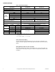
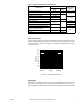
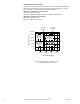
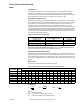
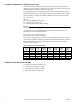
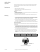
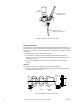
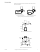
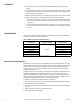
Table Of Contents
- Application
- Features
- Applicable Literature
- SPECIFICATIONS
- VALVE SIZING AND SELECTION
- Water
- Cavitation Limitations on Valve Pressure Drop
- Additional Valve Sizing Information
- INSTALLATION
- Inspection
- Requirements
- Mounting
- 1. The valve should be mounted in a weather-protected area in a location that is within the ambient limits of the actuator. When...
- 1. Apply pipe dope sparingly to all but the last two threads of a properly threaded, reamed, and cleaned pipe. Make sure that pi...
- Table-6 Normal Thread Engagement Between Male Pipe Thread and Valve Body.
- Figure-3 Normal Thread Engagement.
- Figure-4 Installation of Screwed End Valves.
- 1. All parts should be clean to assure the best results.
- 2. The pipe with the companion flanges installed should be properly supported and aligned. Be sure the companion flange is flush with the face of the valve body flange and lined up squarely.
- 3. Use a gasket material (not provided) that is recommended for the medium being handled.
- 4. See Figure-5 for flange and flange bolt details. Figure-5 also shows the proper way a flanged valve should be mounted.
- Figure-5 Installation of Flanged End Valves.
- TYPICAL PIPING
- CHECKOUT
- 1. Make sure the valve stem operates freely before installing the valve linkage and the actuator.
- 2. If the stem does not operate freely, it may indicate that the valve was twisted or crushed during installation or that the stem was bent by rough handling. These conditions may require that the valve be replaced.
- 3. After the piping is under pressure, check the valve body and the connections for leaks.
- 4. After the valve linkage and the actuator are installed, check their operation.
- a. Drive the actuator and run the valve to the stem down position. Make sure the linkage and valve stem move freely. At the stem down position, the valve should shut off the “B” port.
- b. Drive the actuator and valve to the stem up position. Again, the valve stem and linkage should operate smoothly. At the stem up position, the valve should shut off the “A” port.
- 1. Make sure the valve stem operates freely before installing the valve linkage and the actuator.
- MAINTENANCE
- Water System Maintenance
- DIMENSIONAL DATA

F-24393-3 © Copyright 2010 Schneider Electric All Rights Reserved. 5
VALVE SIZING AND SELECTION
Water
Two-position
Two-position control valves are normally selected “line size” to keep pressure drop at a
minimum. If it is desirable to reduce the valve below line size, then 10% of “available
pressure” (that is, the pump pressure differential available between supply and return mains
with design flow at the valve location) is normally used to select the valve.
Proportional to Bypass Flow
Proportional mixing valves used to bypass flow (Figure-6) are piped on the outlet side of the
load to throttle the water flow through the load and therefore control heat output of the load.
These valves are usually selected to take a pressure drop equal to at least 50% of the
“available pressure.” As “available pressure” is often difficult to calculate, the normal
procedure is to select the valve using a pressure drop at least equal to the drop in the coil
or other load being controlled (except where small booster pumps are used) with a minimum
recommended pressure drop of 5 psi (34 kPa). When the design temperature drop is less
than 60°F (33°C) for conventional heating systems, higher pressure drops across the valve
are needed for good results (
Table-3).
*Recommended minimum pressure drop = 5 psi (34 kPa).
Secondary Circuits with Small Booster Pumps: 50% of available pressure difference
(equal to the drop through load, or 50% of booster pump head).
Proportional to Blend Water Flows
Proportional valves used to blend two water flows (Figure-7 and Figure-8) control the heat
output by varying the water temperature to the load at constant flow. These valves do not
require high pressure drops for good control results. They can be sized for a pressure drop
of 20% of the “available pressure” or equal to 25% of the pressure drop through the load at
full flow.
Water Table
See Table-4 for water capacity of VB-9313 series valves.
C
v
Equation
Where:
C
v
= Coefficient of flow
GPM = U.S. gallons per minute (60°F, 15.6°C)
ΔP= Differential pressure in psi (pressure drop)
Table-3 Conventional Heating System.
Design Temperature
Load Drop °F (°C)
Recommended Pressure Drop*
(% of Available Pressure)
Multiplier on
Load Drop
60 (33) or More 50% 1 x Load Drop
40 (22) 66% 2 x Load Drop
20 (11) 75% 3 x Load Drop
Table-4 Water Capacity in Gallons Per Minute for VB-9313 Series.
Valve Body
Part Number
C
v
Rating
Differential Pressure (ΔP in psi)
1 2 3 4 5 6 7 8 9 10 15 20 25 30 35
VB-9313-0-4-12 67 67 95 116 134 150 164 177 190 201 212 259 300 335 367 396
VB-9313-0-5-12 74 74 105 128 148 165 181 196 209 222 234 287 331 370 405 438
VB-9313-0-4-13 91 91 129 158 182 203 223 241 257 273 288 352 407 455 498 538
VB-9313-0-5-13 101 101 143 175 202 226 247 267 286 303 319 391 452 505 553 598
VB-9313-0-5-14 170 170 240 294 340 380 416 450 481 510 538 658 760 850 931 1006
VB-9313-0-5-15 290 290 410 502 580 648 710 767 820 870 917 1123 1297 1450 1588 1716
VB-9313-0-5-16 390 390 552 675 780 872 955 1032 1103 1170 1233 1510 1744 1950 2136 2307
C
v
=
GPM
ΔP=
GPM
C
v
()
GPM = C
v
ΔP
2
ΔP