
User Guide
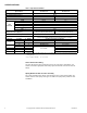
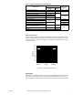
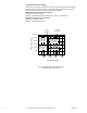
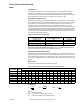
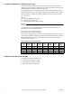
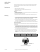
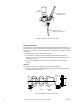
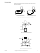
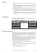
Table Of Contents
- Application
- Features
- Applicable Literature
- SPECIFICATIONS
- VALVE SIZING AND SELECTION
- Water
- Cavitation Limitations on Valve Pressure Drop
- Additional Valve Sizing Information
- INSTALLATION
- Inspection
- Requirements
- Mounting
- 1. The valve should be mounted in a weather-protected area in a location that is within the ambient limits of the actuator. When...
- 1. Apply pipe dope sparingly to all but the last two threads of a properly threaded, reamed, and cleaned pipe. Make sure that pi...
- Table-6 Normal Thread Engagement Between Male Pipe Thread and Valve Body.
- Figure-3 Normal Thread Engagement.
- Figure-4 Installation of Screwed End Valves.
- 1. All parts should be clean to assure the best results.
- 2. The pipe with the companion flanges installed should be properly supported and aligned. Be sure the companion flange is flush with the face of the valve body flange and lined up squarely.
- 3. Use a gasket material (not provided) that is recommended for the medium being handled.
- 4. See Figure-5 for flange and flange bolt details. Figure-5 also shows the proper way a flanged valve should be mounted.
- Figure-5 Installation of Flanged End Valves.
- TYPICAL PIPING
- CHECKOUT
- 1. Make sure the valve stem operates freely before installing the valve linkage and the actuator.
- 2. If the stem does not operate freely, it may indicate that the valve was twisted or crushed during installation or that the stem was bent by rough handling. These conditions may require that the valve be replaced.
- 3. After the piping is under pressure, check the valve body and the connections for leaks.
- 4. After the valve linkage and the actuator are installed, check their operation.
- a. Drive the actuator and run the valve to the stem down position. Make sure the linkage and valve stem move freely. At the stem down position, the valve should shut off the “B” port.
- b. Drive the actuator and valve to the stem up position. Again, the valve stem and linkage should operate smoothly. At the stem up position, the valve should shut off the “A” port.
- 1. Make sure the valve stem operates freely before installing the valve linkage and the actuator.
- MAINTENANCE
- Water System Maintenance
- DIMENSIONAL DATA

F-24393-3 © Copyright 2010 Schneider Electric All Rights Reserved. 9
TYPICAL PIPING
All piping must comply with local codes and ordinances. Refer to Figure-6 through
Figure-8 for typical piping.
Figure-6 Typical Piping for Control of Heating or Cooling Coil.
Coil
Valve
Return
Bypass
Supply Supply
Coil
Bypass
Valve
Return
Stem down flow through coil.
Stem up flow through coil bypass.
Stem up flow through coil.
Stem down flow through coil bypass.
Figure-7 Typical Boiler Hot Water Reset.
Boiler
Valve
System
Pump
AAB
B
Bypass
Return
Supply
Figure-8 Typical Primary-Secondary Piping.
Valve
Secondary
Pump
AAB
B
To Other
Zones
Return
Supply
Coil
From
Other
Zones
Balancing
Cock
Balancing
Cock