
User Guide

PDS • User’s Guide 19
3. Installation
Cable and Adapter Information
• Rack mount each PDS chassis from the front rack ears using four rack screws
(not supplied). Rack threads may be metric or otherwise — depending upon the
rack type.
• Install the lower of the two mounting holes first.
`~ÄäÉ=~åÇ=^Ç~éíÉê=fåÑçêã~íáçå
The table below provides information regarding cables used with the PDS. When
connecting to an PDS, use high-quality shielded cables.
mçïÉê=`çêÇ=~åÇ=iáåÉ=sçäí~ÖÉ=pÉäÉÅíáçå
The PDS is rated to operate with the following specifications:
Input Power: 100-240 VAC, 50-60 Hz
Power Consumption: 100 Watts maximum
The PDS performs line voltage selection automatically. No user controls are required. The
AC power cords must be accessible so that they can be removed during field servicing.
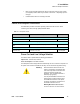
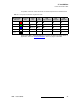
Table 3-1. PDS System Cables
Cable Description Note
Remote Connections
RJ-45 Ethernet Cable For use with PDS Web Interface Customer Supplied
LED Display Connections
RJ-45 Ethernet Cable, cat5 or
better
For connection to your LED display. Customer Supplied
Power Connections
AC Power Cord AC Power, 7 foot, 10A 1 Cord Supplied
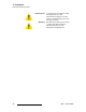
Warning
When the PDS is used in the 230-volt
mode, a UL listed line cord rated for 250
volts at 15 amps must be used and must
conform to IEC-227 and IEC-245
standards. This cord will be fitted with a
tandem prong-type plug.
The rear panel ON/OFF switch does not
disconnect the unit from input AC power.
To facilitate disconnection of AC power,
the power cord must be connected to an
accessible outlet near the unit.
Building Branch Circuit Protection:
For 115 V use 20 A. For 230 V use 8 A.