GRAPHICS 9200 R9001320 OWNER'S MANUAL
BARCO PROJECTION SYSTEMS GRAPHICS 9200 R9001320 OWNER'S MANUAL Date : 030798 Rev : 01 Art. No.
Federal communication commission (FCC statement) This equipment has been tested and found to comply with the limits for a class A digital device, pursuant to Part 15 of the FCC Rules. These limits are designed to provide reasonable protection against harmful interference when the equipment is operated in a commercial environment.
Table of Contents i TABLE OF CONTENTS TABLE OF CONTENTS .............................................................................................................................................................................. i-1 SAFETY INSTRUCTIONS ......................................................................................................................................................................... 1-1 REMARQUE SUR LA SÉCURITÉ .......................................................
Table of Contents Geometry ....................................................................................................................................................................................... 9-8 Shift ............................................................................................................................................................................................... 9-8 Size ..........................................................................................
Unpacking and Dimensions 1 UNPACKING AND DIMENSIONS Unpacking To open the banding, pull on the clip as shown in the first drawing. Pull To open Take the projector out of its shipping carton and place it on a table. For transportation, the projector is mounted on a wooden board with 3 bolts. Use a 13 mm wrench to remove these bolts. When using the projector as a table mounted configuration, always mount the 3 supporting feet (see drawing below). These feet are mounted on the same wooden board.
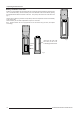
Unpacking and Dimensions Battery installation in the RCU. A battery (not yet installed to save the battery life time) is delivered inside the plastic bag with the power cord. To install the battery, remove the battery cover on the backside of the remote control by pushing the indicated handle a little to the bottom of the RCU. Lift up the top side of the cover at the same time (fig. 1).
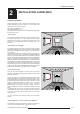
Installation Guidelines 2 INSTALLATION GUIDELINES Installation guidelines Careful consideration of things as image size, ambient light level, projector placement and type of screen to use are critical to the optimum use of the projection system. Max. ambient temperature : 40 °C. Min. ambient temperature : 0 °C. The projector will not operate if ambient air temperature falls outside this range (0°C- 40°C).
Installation Guidelines * Where to install the projector? Inputs and computer video format input compatibility : Definitions of the Abbreviation on drawings Some examples : B = Distance between ceiling and top of the screen or between floor and bottom of the screen. A = Correction value, distance between bottom side of projector (without feed) and middle of the lens. Value to be subtracted from B to obtain the correct installation position.
Location and Functions of Control 3 LOCATION AND FUNCTIONS OF CONTROL Front Panel Terminology 0I 9 $ T h i s d e v i c e c o m p li e s w it h P art 1 5 o f t h e F C C ru l e s .
Location and Functions of Control b. Remote control This remote control includes a battery powered infrared (IR) transmitter that allows the user to control the projector remotely. This remote control is used for source selection, control, adaptation and set up. It includes automatic storing of : - picture controls (Brightness, Sharpness...) - settings Other functions of the remote control are : - switching between standby and operational mode.
Installation Set Up 4 INSTALLATION SET UP The projector can be installed to project images in four different configurations : front/table, front/ceiling, rear/table and rear/ceiling. 5HDU &HLOLQJ )URQW &HLOLQJ 5HDU 7DEOH )URQW 7DEOH To change the Configuration, enter the adjustment mode by pushing ADJUST or ENTER. Highlight Installation by pushing the control disc forward or backward and press ENTER to select. The installation menu will be displayed. ENTER displays the Installation menu.
Installation Set Up 4-2 5975967 BARCOGRAPHICS 9200 221297
Connections 5 CONNECTIONS Power (mains) cord connection Use the supplied power cord to connect your projector to the wall outlet. Plug the female power connector into the male connector at the front of the projector. The power input is auto-ranging from 200 to 240 VAC. This projector may be connected to an IT-power system. T h i s d e vic e co m p lie s w it h P a r t 1 5 o f th e F C C r u le s .
Connections Lamp Run Time When the total run time of the lamp is 970 hours or more, the following message will be displayed for 1 minute. This message will be repeated every 30 minutes. Press EXIT to remove the message before the minute is over. When the total run time of the lamp is 1000 hours or more, the following message, with the exact run time is displayed on the screen. Lamp run time 980 hours Lamp run time is 1000 hours. Operating the lamp longer than 1000 hours may damage the projector.
Connections L On To the Video input : R Composite video signals from a VCR, OFF air signal decoder, etc... 1 x BNC 1.0Vpp ± 3 dB On 9,'(2 6 9,'(2 ,1387 To the S-Video input : S-Video input Separate Y-luma/C-chroma signals for higher quality playback of Super VHS-signals.
Connections RGB Analog Input Module. PROJECTOR MODE: GREEN - OPERATION RED- STANDBY COMMUNICATION PORT RS 232 IN RS232 OUT (800-PERIPHERALS) DIAGNOSTICS IR-ACKNOWLEDGED CODE IR-RECEIVER REMOTE IR-RECEIVED R G B H V R G B H/ C V 6 9,'(2 R 9,'(2 G B V H/ C On Always use an interface when a computer and local monitor have to be connected to the projector.
Connections Push the control disc key forward or backward to select System Settings and press ENTER. ADJUSTMENT MODE Select a path from below : RANDOM ACCESS INSTALLATION SERVICE Use the control disc to select Input Slots by pushing forward or backward and press ENTER. The internal system will scan the inputs and displays the result in the Input Slots menu. Select with or then to return.
Connections Straps on module level : Floating or non-floating input. R-Y : J3 : strap "yes" : non floating Y : J4 : strap "yes" : non floating B-Y : J5 : strap "yes" : non floating S : J6 : strap "yes" : non floating )ORDWLQJ RU QRQ IORDWLQJ LQSXW Non-Floating strap strap strap strap "no" "no" "no" "no" : : : : floating floating floating floating Floating Factory preset : strap "yes", non floating input Sync selection. J8 : strap "no" : separate sync strap "yes" : sync on Y.
Connections Straps on module level : - 6 \ Q F V H OH F WLR Q Floating or non-floating input.
Connections Connecting a RCVDS 05 to the projector. - Up to 10 inputs (20 when video inputs) with the RCVDS 05 and 90 inputs when RCVDS's are linked via the expansion module. - Serial communication with the projector. - Remote control buttons on the RCVDS to control the projector (source selection and analog settings). - The selected source number will be displayed on a 2 digit display and the selected input module will be indicated with a LED on the rear.
Controlling 6 CONTROLLING The projector can be controlled with a. The RCU b. The hardwired RCU (cable is not included) c. The local keypad. c) Point the front of the RCU directly at one of the IR sensors of the projector. IR sensor IR sensor Controlling the projector with the RCU and the hardwired RCU is equal.
Controlling How to Display a Projector Address? Press the ADDRESS key (recessed key on the RCU) with a pencil. The projector's address will be displayed in a 'Text box'. This text box disappears after a few seconds. To continue using the RCU, it is necessary to enter the same address with the digit buttons (address between 0 and 9). For example : if the Address key displays projector address 003, then press "3" digit button on the RCU to set the RCU's address to match the projector's address.
Start up of the Adjustment Mode 7 START UP OF THE ADJUSTMENT MODE Adjustment Mode All source parameters, picture tuning and geometry are made while in the 'Adjustment Mode' . Press the ADJUST or ENTER key to enter the 'Adjustment mode'. You are now in the 'Adjustment Mode'. The control disc (RCU) or '+ or '-' keys (local keypad) are used to make menu selections and also for adjustments. The ENTER and EXIT keys are used to move forward and backward through the menu structure.
Start up of the Adjustment Mode 7-2 5975967 BARCOGRAPHICS 9200 221297
Random Access Adjustment Mode 8 RANDOM ACCESS ADJUSTMENT MODE Starting up the Random Access Adjustment Mode ADJUSTMENT MODE Push the control disc up or down to highlight 'Random Access' and then press ENTER. Select a path from below : RANDOM ACCESS INSTALLATION SERVICE LOAD EDIT Source 01 Select with or then to return.
Random Access Adjustment Mode Highlight File Service by pushing the control disc up or down and press ENTER to select. The File service menu will be displayed. ENTER displays the File Service menu; EXIT returns to the Path selection menu. ADJUST returns to operational mode. The following file manupulations are possible : - Load : installation of a file for a new source. - Edit : editing a loaded file to the source specs. - Rename : renaming a file. - Copy : copying a file to a new file.
Random Access Adjustment Mode The file name will be displayed in the upper right corner.
Random Access Adjustment Mode Options Source Number : The source number of a non-active source can be changed to any other source number. This makes it possible to create a file for future source numbers. EDIT FILE OPTIONS Source number 1 Clamp position [leading] Clamp width [1] Field polarity inverted [no] Vertical refresh [sync] Vert. sync polarity [leading] Clamp Position : Clamping determines the black level of the signal.
Random Access Adjustment Mode Rename To change the name of a selected file. Use the control disc to select RENAME and press ENTER. The Rename selection menu will be displayed. Use the control disc to select a file name and press ENTER to select. The Rename menu will be displayed with the selected file name already filled in in the 'From file name :' area and in the 'To file name :' area. FILE SERVICE LOAD EDIT RENAME COPY DELETE Select with or RENAME FILE then to return.
Random Access Adjustment Mode Delete To delete a selected file out of the list of files. Use the control disc to select DELETE and press ENTER. The delete selection menu will be displayed. Push the control disc up or down to select a file and press ENTER. If [All] is selected, your password has to be entered before all files will be deleted. FILE SERVICE LOAD EDIT RENAME COPY DELETE OPTIONS Select with or then to return.
Random Access Adjustment Mode Sync slow/fast PICTURE TUNING Highlight sync by pushing the control disc up or down and press ENTER to toggle between SLOW and FAST. SYNC [FAST] STILL VIDEO [ON] COLOR TEMPERATURE GAMMA Select with or then to return. Still Video PICTURE TUNING This function is only used for stationary interlaced images. Highlight Still Video by pushing the control disc up or down and press ENTER to toggle between ON and OFF.
Random Access Adjustment Mode Gamma With the gamma correction adjustment, it is possible to choose between higher color saturation (lower image values) and softer colors (higher gamma values). PICTURE TUNING SYNC [SLOW] STILL VIDEO [ON] COLOR TEMPERATURE GAMMA To change the gamma value, highlight Gamma by pushing the control disc up or down and press ENTER. GAMMA = 2.2 3 Geometry Highlight Geometry by pushing the control disc up or down and press ENTER to select the geometry selection menu.
Random Access Adjustment Mode Side Keystone GEOMETRY Highlight Side Keystone by pushing the control disc up or down and press ENTER to select. SHIFT SIZE SIDE KEYSTONE BLANKING OPTIONS The side keystone adjustment is used to align the image if the projector is mounted at a non standard projection angle. Select with or then to return. Push the control disc to the right or to the left to adjust the keystone of the image.
Random Access Adjustment Mode Adjustment of the blanking on the top of the image BLANKING TOP BOTTOM LEFT RIGHT Adjustment of the blanking on the bottom of the image Correct by pushing the control disc up or down Select with or then to return. Adjustment of the blanking on the left side Adjustment of the blanking on the right side Correct by pushing the control disc to the right or to the left Options Highlight Options by pushing the control disc up or down and press ENTER.
Installation Mode 9 INSTALLATION MODE Starting up the Installation Mode Push the control disc up or down to highlight Installation and then press ENTER. ENTER continues to the Installation mode selection menu. EXIT returns to operational mode. The following item can be selected in the Installation mode : ADJUSTMENT MODE Select a path from below : RANDOM ACCESS INSTALLATION SERVICE Source 01 Input slots : to set up the input priority. Convergence : to align the red, green and blue image.
Installation Mode Convergence INSTALLATION Highlight "Convergence" by pushing the control disc up or down and press ENTER to display the convergence selection menu. Every LCD panel has 6 adjustment screws. By turning these screws you change the relative position of the panels and converge the image. Always start with the adjustment of the green panel. When the green image is correctly focused, it will later on be used as the reference image to converge the red and blue image.
Installation Mode The three alignments influence each other, therefore repeat if necessary the above three steps (b,c and d). When the green pattern is correctly focused, press EXIT to return to the Convergence menu. Red on green convergence. Use the control disc to hightlight Red on green and press ENTER to display the Red on green test pattern. The longest lines are the red lines. These lines must be converged with the green lines. The drawn screws and numbers are displayed in red. Follow next steps : a.
Installation Mode Blue on green convergence. Use the control disc to highlight Blue on green and press ENTER to display the Blue on green test pattern. CONVERGENCE Repeat the same procedure as for Red on green lines but read blue when red is indicated. GREEN BLUE ON GREEN RED ON GREEN HATCH Select with or then to return. To check the result of the convergence adjustments, highlight Hatch and press ENTER. A hatch pattern will be displayed on the screen. ENTER : displays a hatch pattern.
Service Mode 10 SERVICE MODE Starting up the Service Mode Push the control stick forward or backward to highlight Service and then press ENTER. ADJUSTMENT MODE Select a path from below : GUIDED RANDOM ACCESS INSTALLATION SERVICE Some items in the Service mode are password protected (when the password function is active). Enter your password to continue. All other password protected items are now available if you stay in the adjustment mode. Source 01 Select with or then to return.
Service Mode SERVICE IDENTIFICATION CHANGE PASSWORD CHANGE LANGUAGE CHANGE PROJ. ADDRESS CHANGE BAUDRATE PC RESET LAMP RUNTIME LAMP RUNTINE HISTORY LAMP POWER : 1500W MORE... Select with or then to return. PANEL ADJUSTMENT RED COARSE PRESET INPUT BALANCE WHITE BALANCE FIELD FLICKER BLACK LEVEL TOP BLACK LEVEL BOTTOM GAIN TOP GAIN BOTTOM Change color+pattern with or Select with or then to return.
Service Mode Change Password This item is password protected when the password strap is installed. How to enable or disable the password function ? Loosen the locking screws. The password function is enabled when the password strap on the controller module is installed. To get acces to the controller module, handle as follows : 0 I 9 $ This device complies with Part 15 of the FCC rules.
Service Mode How to change the password ? Highlight Change password by pushing the control stick forward or backward and press ENTER to display the Change Password menu. ENTER displays the Change Password menu EXIT returns to the adjustment selection menu. ADJUST returns to operational mode. The old password is displayed and can be changed by entering the digit with the numeric keys of the RCU or local keypath. SERVICE IDENTIFICATION CHANGE PASSWORD CHANGE LANGUAGE CHANGE PROJ.
Service Mode The following baud rates are available : - 9600 - 4800 - 2400 - 1200 - 600 - 300 - 150 - 75 The actual baud rate will be highlighted. To change the baud rate, push the control stick forward or backward and press ENTER to accept the new baud rate setting. CHANGE BAUDRATE PC 9600 4800 2400 1200 600 300 150 75 Select with or to accept to return. Reset Lamp Runtime Reset lamp run time is only allowed when a new lamp is installed.
Service Mode Panel Adjustments SERVICE Changing these settings may seriously affect the performance of the projector. All panel adjustments are factory adjusted. If not really necessary, do not touch one of these adjustments. They are useful when a new panel is installed. PANEL ADJUSTMENTS PRESET INPUT BALANCE 60Hz TRACKING I2C DIAGNOSIS Highlight Panel Adjustments by pushing the control stick forward or backward and press ENTER Select with or then to return. MORE...
Appendix A : Standard Source Set Up Files A STANDARD SOURCE SET UP FILES NAME RESOLUTION FVERT FHOR FPIX Hz kHz MHz CGA 640 X 200 59,924 15,700 14,318 912 640 262 200 NTSC 675 X 240I 29,970 15,734 13,500 858 720 263 240 NTSC_2 675 X 240I 29,970 15,734 13,500 858 720 263 240 NTSC_3 675 X 240I 29,970 15,734 13,500 858 720 263 240 PAL 675 X 278I 25,000 15,625 13,500 864 720 313 278 PAL_2 675 X 278I 25,000 15,625 13,500 864 720 313 278 PAL_3 675 X 278I 25,000 15,625 1
Appendix A : Standard Source Set Up Files A-2 NAME RESOLUTION FVERT Hz FHOR kHz FPIX MHz PTOT PACT LTOT LACT XGA_72 1024 X 768 71,955 58,140 80,000 1376 1024 808 768 SUP_MAC 1024 X 768 60,000 48,780 63,999 1312 1024 813 768 XGA_70 1024 X 768 70,000 57,050 78,044 1368 1024 815 768 MAC_POR 640 X 870 74,996 68,846 57,280 832 918 870 INTER_GR 1184 X 886 67,170 61,796 92,941 1504 1184 920 886 EWS_50 1280 X 1024 50,000 52,350 87,948 1680 1280 1047 1024 EWS_60 1
Lenses B LENSES Focusing the lens Loosen the fastener ring of the lens by turning counter clockwise. Focus the image by turning the lens barrel to the left or the right. Attention : Do not turn out the lens too far, otherwise it will fall out of the lens holder. When the image is focused, secure the correct position of the lens with the fastener ring by turning this ring clockwise. Lens Cleaning Procedure Cleaning procedure for HD(1.5-3:1) lens and HD(3-5.3:1) lens.
Lenses Lenses N ame Len gth len s mm (in ch ) diam. len s mm (in ch ) w eigh t kg (lbs) order n u mber HD (1.2:1) 253 (9.96) 189 (7.44) 8.7 (19.2) R9829200 HD (2.2:1) 235 (9.25) 137 (5.39) 7.5 (16.5) R9829060 HD (3.3:1) 149 (5.87) 152 (5.98) 4.3 (9.5) R9829075 HD (4.0:1) 165 (6.50) 152 (5.98) 3.5 (7.7) R9829145 HD (5:1) 238 (9.37) 164 (6.46) 5.1 (11.2) R9829180 HD (7:1) 373 (14.68) 196 (7.72) 12.0 (26.4) R9829090 HD (1.5-3:1) 460 (18.11) 260 (10.24) 13.0 (28.
Source Numbers 90 - 99 C SOURCE NUMBERS 80 - 89 AND 90 - 99 Projector without any 800 peripheral connected. The source numbers 80 - 89 and 90 - 99 do not correspond to physical inputs. An additional adjustment file can be created for these source numbers. This file can contain different settings. The relationship between sources 0 - 9 and 90 - 99 or between 0 - 9 and 80 - 89 is shown in the diagram below.
Source Numbers 90 - 99 Source numbers 81 - 84 Only valid if no input module is connected to slot 81 - 84 of a RCVDS05. The source numbers 81 - 84 correspond to the physical inputs 1 - 4 of the projector. e.g. When slot 1 of the projector has to be selected, key in source number 81. The relationship between the sources of slot 1 - 4 of the projector with 800 peripheral is shown in the table below.
5&8 5&8 ,1 3 8 7 62 8 5 & (6 ,1 3 8 7 62 8 5 &(6 352-(&725 ,1387 62 8 5&(6 5975967 BARCOGRAPHICS 9200 221297 5&9'6 352-(&725 3 3 ,1387 62 8 5&(6 5&9'6