BarcoiQ GRAPHICS 500 Owner’s Manual R9002930 R5976367/10 01/02/2007
Product revision Software version: V3.10 Barco nv Presentations Noordlaan 5, 8520 Kuurne Phone: +32 56.36.82.11 Fax: +32 56.35.86.51 E-mail: presentations.bid@barco.com Visit us at the web: www.barco.
Copyright © All rights reserved. No part of this document may be copied, reproduced or translated. It shall not otherwise be recorded, transmitted or stored in a retrieval system without the prior written consent of Barco. Federal Communications Commission (FCC Statement) This equipment has been tested and found to comply with the limits for a class A digital device, pursuant to Part 15 of the FCC rules.
Table of contents TABLE OF CONTENTS 1. Packaging and Dimensions . . . . . . . . . . . . . . . . . . . . . . . . . . . . . . . . . . . . . . . . . . . . . . . . . . . . . . . . . . . . . . . . . . . . . . . . . . . . . . . . . . . . . . 5 1.1 1.2 1.3 1.4 Box content . . . . . . . . . . . . . . . . . . . . . . . . . . . . . . . . . . . . . . . . . . . . . . . . . . . . . . . . . . . . . . . . . . . . . . . . . . . . . . . . . . . . . . . . . . . . . . . . . . . . . . . . . . . . . . . . . . . . . . . . . .
Table of contents 7. Image Menu . . . . . . . . . . . . . . . . . . . . . . . . . . . . . . . . . . . . . . . . . . . . . . . . . . . . . . . . . . . . . . . . . . . . . . . . . . . . . . . . . . . . . . . . . . . . . . . . . . . . . . . . 57 7.1 Settings . . . . . . . . . . . . . . . . . . . . . . . . . . . . . . . . . . . . . . . . . . . . . . . . . . . . . . . . . . . . . . . . . . . . . . . . . . . . . . . . . . . . . . . . . . . . . . . . . . . . . . . . . . . . . . . . . . . . . . . . . . . . . .
Table of contents A. Cleaning the dustfilters. . . . . . . . . . . . . . . . . . . . . . . . . . . . . . . . . . . . . . . . . . . . . . . . . . . . . . . . . . . . . . . . . . . . . . . . . . . . . . . . . . . . . . . . . . 125 A.1 A.2 Dustfilters . . . . . . . . . . . . . . . . . . . . . . . . . . . . . . . . . . . . . . . . . . . . . . . . . . . . . . . . . . . . . . . . . . . . . . . . . . . . . . . . . . . . . . . . . . . . . . . . . . . . . . . . . . . . . . . . . . . . . . . . . . .125 Cleaning . .
Table of contents 4 R5976367 BARCOIQ GRAPHICS 500 01/02/2007
1. Packaging and Dimensions 1. PACKAGING AND DIMENSIONS Overview • Box content • Projector Packaging • Lens Packaging • Dimensions 1.1 Box content CEE7 European power plug to connect the power cord to the wall outlet. ANSI 73.11 American power plug to connect the power cord to the wall outlet. Content • 1.2 1 projector (weight ± 12,6 kg or 27.8 lbs) • 1 remote control unit RCU + 2 batteries. • 2 power cables with outlet plug type CEE7 and ANSI 73.11.
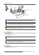
1. Packaging and Dimensions R824561 R824562 Projector PULL TO OPE R824518 (+ cable basket R724408 Image 1-1 R825784 Image 1-2 Save the original shipping carton and packing material, they will be necessary if you ever have to ship your projector. For maximum protection, repack your projector as it was originally packed at the factory. Save the original shipping carton and packing material, they will be necessary if you ever have to ship your projector.
1.
1. Packaging and Dimensions 8 Lens length of projector combinable with cable basket Remarks SVD(2-2.5:1) 545mm YES Length with cable basket = 565mm QVD(1.3-1.8:1) 600mm YES QVD(1.9-2.6:1) 590mm YES QVD(3.0-6.0:1) 620mm YES QVD(0.85:1) 545mm NO QVD(7.
2. Installation Guidelines 2. INSTALLATION GUIDELINES Overview • Safety warnings • Installation guidelines • Projector configurations • Lenses • Batteries 2.1 Safety warnings WARNING: Before installing the projector, read first the safety instructions in the safety manual (R5975258) delivered with the projector. Insure that the projector is installed in an easy to evacuate room in case of a lamp explosion. Mercury Vapor Warnings Keep the following warnings in mind when using the projector.
2. Installation Guidelines has been specifically designed for cleaning optical parts, never use industrial strength cleaners on a projectors optics as these will degrade optical coatings and damage sensitive optoelectronics . Failure to take suitable precautions to protect the projector from the effects of persistent and prolonged air contaminants will culminate in extensive and irreversible ingrained optical damage.
2.
2.
2. Installation Guidelines PD a SH front plate P S A B CD=B-A F b SW S SW c SH F Image 2-3 100% OFF Axis installation a b c x p s F side view top view back view optical axis projection lens projector screen floor CAUTION: Only for iQ Pro: The harddisk in the IQ Pro server is formatted in horizontal position but can operate in all axes (6 directions). The projector should not be tilted more then +/- 5 degrees from these positions, otherwise error rates will increase.
2. Installation Guidelines CAUTION: Floor Never place the projector on either side ! Floor Image 2-4 2.4 Lenses Overview 2.4.1 • Lenses • Lens formulas • Lens installation • Removing the lens • Cleaning the lens Lenses Available lenses The following lenses are available, or will become available (contact a BARCO service center) as an option : Lenses Standard version QVD(0.85:1) R9841220 QVD(1.3-1.8:1) R9840950 QVD(1.9-2.6:1) R9840960 QVD(3.0-6.
2. Installation Guidelines 2.4.2 Lens formulas Formulas Metric Formulas (meter) Inch formulas (inch) QVD(0.85:1) PD = -0.034 + 0.801 x SW + 0.0086 /SW PD = -1.34 + 0.801 x SW + 13.35 /SW QVD(1.3-1.8:1) PDmin = 0.019 + 1.216xSW + 0.028/SW PDmin = 0.75 + 1.216xSW + 43.4/SW PDmax = -0.001 + 1.584xSW + 0.074/SW PDmax = -0.04 + 1.584xSW + 115/SW PDmin = 0.052 + 1.731xSW - 0.014/SW PDmin = 2.05 + 1.731xSW - 21.7/SW PDmax = 0.11 + 2.33xSW - 0.059/SW PDmax = 4.33 + 2.33xSW - 91.8/SW PDmin = 0.
2. Installation Guidelines Image 2-5 Image 2-6 CAUTION: Never transport the projector (or the whole unit) with the lens mounted on it ! Always remove the lens and transport it separately. 2.4.4 Removing the lens How to remove the lens ? 1. Slide the lens door to the left. 2. Unlock the lens by pulling the handle located on the right side of the projector (image 2-7) 3.
2. Installation Guidelines 2.4.5 Cleaning the lens To minimize the possibility of damage to optical coatings, or scratches to lens surfaces, we have developed recommendations for cleaning. FIRST, we recommend you try to remove any material from the lens by blowing it off with clean, dry deionized air. DO NOT use any liquid to clean the lenses. Necessary tools Toraysee TM cloth (delivered together with the lens kit). Order number : R379058. How to clean the lens ? Proceed as follow : 1.
2.
3. Connections 3. CONNECTIONS Overview • Power connection • Input source connection • 5-Cable input • Composite Video Input • S-Video input • Digital Visual Interface (DVI) input • Computer input • Serial Digital Interface (Optional) • Audio input/Output (Optional) • Communications Connections • Extended configuration 3.1 Power connection AC power (mains) cord connection Use the supplied power cord to connect your projector to the wall outlet.
3. Connections 3.2.1 Input section Input Layers The input section is divided in layers, each of them regrouping several inputs, this architecture allows the input section to be upgraded at any time with an optional analog or digital layer. 1. Layer 1: analog layer containing analog data and video inputs 2. Layer 2: a hybrid layer containing 2 digital and 1 analog input 3. Layer 3 : is an optional layer, it may be an Audio & Video analog layer or a SDI digital layer.
3. Connections Layer 3 can be an optional audio&video layer or an optional SDI (SDI Input/Output) Image 3-3 source input section with optional SDI layer A cable cover is supplied with the projector and can be fitted on the front of the projector Image 3-4 Cable basket : the white arrow shows the cables leaving the projector A B 3.3 Front view Back view 5-Cable input Input specifications The 5-cable input section is made of 5 BNC input terminals. 0.
3. Connections Image 3-5 Component Video In Component Video the term component describes a number (3) of elements that are needed to make up the video picture, these components are R-Y/Y/B-Y.
3. Connections Image 3-6 How to select a Composite Video Input ? 1. Press 3 on the RCU Note: Another way for selecting this input is via the Menu. The projector allows the input of more composite video signals (up to 7 composite video signals). "5 cable extended configuration", page 27 This note is not valid for the Pro version : The Audio&Video optional layer(3) allows the use of an additional Video BNC input (referred to as Video2).
3. Connections Which signal can be connected ? Standard S-Video (S-VHS) with separate Y(luma) and C (chroma) signals. How to select the S-Video input ? 1. Press 4 on the RCU Note: Another way for selecting this input is via the Menu. The projector allows the input of more S-Video signals (up to 3 composite video signals).
3. Connections 3.7 Computer input Input specification TTL sync input : U min = 2.0 V RGB input = 0.7 V pp ± 3dB Image 3-9 What can be connected ? • RGBHV • RG SB Composite sync only possible on Green How to select a computer input ? 1. Press 2 on the RCU Note: Another way for selecting this input is via the Menu. 3.8 Serial Digital Interface (Optional) SDI Serial Digital Interface Input specifications SDI input : BNC SDI output : BNC (=loop through) typical : 0.
3. Connections Image 3-10 How to select the SDI input 1. Press 7 on the RCU Note: Another way for selecting this input is via Source on the local keypad or via the Menu. The SDI is located on Layer3 which is an optional Layer. 3.9 Audio input/Output (Optional) Input specification Typical = 200 mV Max = 4V pp Mono/Stereo Output specification V in +20dB / -∞ dB Max = 4 V pp Mono/Stereo (selectable in menu) How to select the audio input ? 1.
3. Connections 3.10 Communications Connections Overview • RS232 IN connection 3.10.1 RS232 IN connection What can be connected to the RS232 IN connection ? The RS 232 IN connections allows the projector to communicate with a Computer e.g. IBM PC or Apple Macintosh. Image 3-12 Applications of the RS232 connection Remote control: • easy adjustment of projector via IBM PC (or compatible) or MAC connection. • address range from 1 to 255 • allow storage of multiple projector configurations and set ups.
3.
3. Connections Signals Y C Composite Video Video - Composite Video - Video S-Video Table 3-3 Extended configuration of the S-Video input: the first column gives the possible signals, and the first row the S-Video inputs pins. How to set up the S-Video extended configuration ? 1.
3.
4. Getting started 4. GETTING STARTED Overview 4.1 • RCU & Local keypad • Terminology overview • Switching on • Lamp runtime • Lamp error • Quick set up adjustments • Projector address • Controlling the projector • Digital Zoom • Menu structure • Using the menu • Using the Dialogboxes RCU & Local keypad How controlling the projector ? The projector can be controlled by the local keypad or by the remote control unit.
4. Getting started Image 4-1 Local keypad layout Remote control functions. This remote control includes a battery powered infrared (IR) transmitter that allows the user to control the projector remotely. This remote control is used for source selection, control, adaptation and set up. It includes automatic storing of picture controls (Brightness, Sharpness...) and settings. Other functions of the remote control are : • switching between stand by and operational mode.
4. Getting started 4.2 Terminology overview Overview The following table gives an overview of the keys. Image 4-2 1 Function keys user programmable keys with functions for direct access. 2 MENU Menu key, to enter or exit the Toolbar menu. 3 Address key (recessed key), to enter the address of the projector (between 0 and 9). Press the recessed address key with a pencil, followed by pressing one digit button between 0 and 9.
4. Getting started 10 Lens control use these buttons to obtain the desired ZOOM, SHIFT, FOCUS. 11 VOL use this button to obtain the desired sound level (audio = optional) 12 Picture controls use these buttons to obtain the desired picture analog level. 13 DIGI ZOOM allows a digital Zoom of a part of the image 14 FREEZ press to freeze the projected image. 15 PIP allows to activate the PICTURE IN PICTURE mode 16 ENTER to confirm an adjustment or selection in the MENU.
4. Getting started If the Security mode is enabled, a textbox will be displayed for PIN code entry, see Security setting in the Installation menu 4.4 Lamp runtime x To generalize for the different projector types, x refers here to the maximum run time of the lamp. Lamp runtime indication while running Independently of the lamp mode, when the total runtime of an active lamp (lamp1 for example) is (x-30) hours or more, a warning message will be displayed.
4. Getting started The total lifetime of the lamp for a safe operation is “x” hours max, do not use it longer. Always replace with a same type of lamp. Call a BARCO authorized service technician for lamp replacement. BarcoIQ x ( Max lamp runtime, in hours) 210L 6000 350 3000 500 1500 Table 4-3 Maximum runtime for the different BarcoIQ projectors When the lamp runtime reaches “x” hours the projector switches automatically to the other lamp, being lamp2..
4. Getting started Image 4-10 The message will dissapear after 2 minutes, it can also be escaped. The projector will switch to single lamp mode and displays an icon (right top corner of the screen) representing a crossed out lamp, that way informing the user of an earlier lamp error. The icon can always be removed via the Clear lamp error function in the Lamp menu. WARNING: 4.6 In case of lamp error contact a Barco authorized technician. Quick set up adjustments Overview 4.6.
4. Getting started Image 4-11 When using the remote control, make sure you are within the effective operating distance. The operating distance may be up to 15 m (50ft). The remote control unit will not function properly if strong light strikes the sensor window or if there are obstacles between the remote control and the IR sensor. How to connect ? 1. Plug one end of the remote cable in the connector on the bottom of the RCU. 2.
4. Getting started A B C D Image 4-13 Stereo jack pin configuration A B C D tip: Left channel ring: right channel screen: common (GND) external switch The Remote connection uses a standard two wire cable terminated on each end with a 3.5 mm male (mono/stereo) phone jack. This cable is not delivered but is available in most electronical or audio shops. 4.7 Projector address Overview • Address setting • Displaying and Programming addresses into the RCU 4.7.
4. Getting started Some projectors may operate in domestic environments where other equipments may listen to the common address “0” , therefore the common address can also be set to “1”. 4.7.2 Displaying and Programming addresses into the RCU Displaying the Projector Address on the Screen. 1. Press the Address key (recessed key on the RCU) with a pencil.
4. Getting started Sharpness Use the + button for a sharper picture. Use the - button for a softer picture. Phase Use the + or - button to adjust the phase. Gamma Use the + button for a higher gamma Use the - button for a lower gamma Freeze Press Freeze to freeze the displayed image. The Pause Key When the Pause key is pressed, the image projection is stopped, a black screen will be displayed To restart the image projection: • Press PAUSE key • Press BACK key • Select a source number 4.
4. Getting started Three suspension points indicate that the menuitem hides a dialogbox or a textbox. Image 4-15 The menus inserted in this manual are of the advanced type: all the items are visible The menus seen by a standard user on the screen will hence not correspond with the menus in the manual i.e. the advanced items will not be visible, they will be replaced with "More..." Greyed out menus or items are not available in this software version How to pull down a menu ? 1.
4. Getting started Image 4-16 Entering numeric values using the arrow keys on the remote control 1. Press ENTER to activate the input field. 2. Press ←or → to select the digit to be changed (image 4-17) 3. Press ↓ or ↑ to increase or decrease the value Image 4-17 Entering numeric values using the arrow keys on the local keypad 1. Press ENTER to activate the input field. 2. Press ←or → to select the digit to be changed 3.
4.
5. Source Selection 5. SOURCE SELECTION Overview • 5.1 Source selection • Composite Video • S-Video • The Video Selector Source selection Selecting a source The Source selection menu allows to select one of the different sources. Another method to select an input source is via the remote control using the numeric keys or by using the local keypad.
5. Source Selection Image 5-2 The Barco logo on the menu indicates the presence of a signal, the digit indicates the shortcut key on the RCU. The 3 first sources (Data on BNC’s, Component Video & RG(s)B) refer to the 5-cable input, the position of the indication “1” will always show which BNC configuration is selected.
5. Source Selection Image 5-3 Adjustments on a Composite video signal The projectors allows different adjustments on a composite video signal.
5. Source Selection Image 5-4 The S-Video sources can also be selected using the video selector or via the dedicated key 4 on the RCU. Key 4 allows to browse through the active S-Video inputs when the extended mode is checked in Video Selector. 5.
5. Source Selection A A B B C C D E D E Image 5-7 Image 5-6 If the Audio/Video option is installed the Video Selector is updated with the additional Video & S-Video input Image 5-8 How to select an input on the Video Selector ? 1. Use ←or→ to browse through the different inputs 2. Press ENTER Use MENU or BACK to exit the Video Selector How to disable the extended Video Selector 1. Use the arrow keys to select the Extended checkbox 2.
5.
6. General Menu 6. GENERAL MENU Overview • 6.1 Pause • Freeze • Standby Timer • Audio (Optional) • Identification Pause Interrupting the image projection With the Pause function, the image projection can be stopped, the projector remains with full power for immediate restart. The projection is interrupted by means of a mechanical shutter cutting the light beam. How to interrupt the image projection ? 1. Press MENU to activate the Tool bar 2. Press → to select General 3.
6. General Menu Image 6-2 The image can also be frozen using the FREEZE key on the RCU 6.3 Standby Timer Purpose of the Standby Timer If there is no signal, and the standby timer is enabled, a dialogbox is displayed and the projector will shut down after a determined time. The countdown time can be set in a dialog box in a range from 180 to 3600 seconds (default value = 300). The Timer can also be disabled. How to enable the timer ? 1. Press MENU to activate the Tool bar 2. Press → to select General 3.
6. General Menu Image 6-4 6.4 Audio (Optional) Overview • Audio Setup • Audio Settings 6.4.1 Audio Setup What can be done ? Layer 3 allows the input of 4 audio signals, each of them can be linked to the corresponding (video or data) source signal. it is also possible to link multiple audio signals to one video (or data) source signal, this can be useful in case of teleconferencing. The configuration has to be done in the Audio Setup menu Starting the Audio Setup menu 1.
6. General Menu Image 6-6 How to mute an Audio channel ? 1. use the arrow keys to select the desired mute box 2. Press ENTER How to link an audio input to a source ? 1. use the arrows to select the desired scroll box 2. Press ENTER to open the scroll box 3. use ↑ or ↓ to select the source 4. Press ENTER When the source switching mode is the fade in/out mode, the audio switching will also be done using a fade in/out effect. 6.4.2 Audio Settings Audio Settings 1. Press MENU to activate the Tool bar 2.
6. General Menu Image 6-8 6.5 Identification The projector’s identification screen The identification screen displays the projector’s main characteristics How to display the identification screen ? 1. Press MENU to activate the Tool bar 2. Press → to select General 3. Press ↓ to Pull down the General menu 4. Use ↑ or ↓ to select Identification (image 6-9) 5. Press ENTER to activate the function On the screen appears a text box. In this case the projector is an iDR500 (image 6-10) 6.
6.
7. Image Menu 7. IMAGE MENU Overview • Settings • Aspect ratio • Show native resolution • Keystone • Color temperature • Filmmode detection • Blanking • Input balance • AGC on Video • Manual Gain Control 7.1 Settings Overview • Contrast • Brightness • Color • Tint (hue) • Sharpness • Gamma • Phase • Noise reduction What can be done ? Correct image settings are important for a good image reproduction. The image settings are made through a dialog box with a scroll bar.
7. Image Menu 7.1.1 Contrast Contrast adjustment Adjust the contrast to “brighten” the white parts of the image. It is recommended to adjust the brightness before adjusting the contrast. How to change the contrast 1. Press MENU to activate the Toolbar 2. Press → to select the Image item 3. Press ↓ to Pull down the Image menu 4. Use ↑ or ↓ to select settings 5. Press → to pull down the menu 6. Use ↑ or ↓ to select Contrast 7. Press ENTER On the screen appears now a sliderbox (image 7-3) 8.
7. Image Menu How to change the Color ? 1. Press MENU to activate the Toolbar 2. Press → to select the Image item 3. Press ↓ to Pull down the Image menu 4. Use ↑ or ↓ to select settings 5. Press → to pull down the menu 6. Use ↓ or ↑ to select Color 7. Press ENTER On the screen appears now a sliderbox (image 7-5) 8. Use ←or → , the numeric keys on the remote, or the keypad to change the Color Image 7-5 7.1.4 Tint (hue) How to change the Tint ? 1. Press MENU to activate the Toolbar 2.
7. Image Menu 5. Press → to pull down the menu 6. Use ↓ or ↑ to select Gamma 7. Press ENTER On the screen appears now a sliderbox 8. Use ←or → , the numeric keys on the remote, or the keypad to change the Gamma 7.1.7 Phase Phase adjustment A bad phase adjustment will result in bad transitions and sometimes noise (text can end to be unclear). How to change the Phase ? 1. Press MENU to activate the Toolbar 2. Press → to select the Image item 3. Press ↓ to Pull down the Image menu 4.
7. Image Menu 4:3 16:9 2.35:1 Image 7-7 Common non- anamorphic aspect ratios in DVD sources 16:9 2.
7. Image Menu Projector setting Source 4:3 4:3 16:9 5:4 16:9 2.35:1 16:9 anamorphic 2.35:1 anamorphic Image 7-9 Possible aspect ratio settings and their effect on different sources in the iQ. We can conclude that the thumb rule for DVD projection is to always leave the projector in 4:3 format except when dealing with anamorphic sources where the 16:9 setting allows the best reproduction. The Auto function calculates an aspect ratio based on the information stored in the image files.
7. Image Menu Image 7-10 The aspect ratio settings are greyed out in case the Show native resolution or the Full screen representation setting is enabled. How to set a custom Aspect ratio ? 1. Press MENU to activate the Tool bar 2. Press → to select Image 3. Press ↓ to Pull down the Image menu (image 7-11) 4. Use ↑ or ↓ to select Aspect ratio 5. Use → open the Aspect ratio menu 6. Use ↑ or ↓ to select Custom 7. Press ENTER to confirm A dialog box is displayed (image 7-12) 8.
7. Image Menu Image 7-12 7.3 Show native resolution Graphics Native resolution of the LCD panels = 1024 pixels x 768 pixels (4:3) Reality(SXGA) Native resolution of the LCD panels = 1366 pixels x 1024 pixels (4:3) Reality(SXGA+) Native resolution of the LCD panels = 1400 x 1050 pixels (4:3) What can be done ? The aim here is to always show the resolution of the source independently of the resolution of the LCD panels.
7. Image Menu 4. Use ↑ or ↓ to select Show native resolution (image 7-13) 5. Press → to pull down the menu 6. Use ↓ or ↑ to select On 7. Press ENTER A white bullet shows the selection Image 7-13 The default mode is used if the show native resolution and the full screen function are off.
7. Image Menu Image 7-14 Image 7-15 Image 7-16 Top adjustment of the keystone Image 7-17 Bottom adjustment of the keystone 7.
7. Image Menu 4. Use ↑ or ↓ to select Color temperature 5. Press → to pull down the menu 6. Use ↓ or ↑ to select the desired preset color temperature 7. Press ENTER The color temperature of the image is adapted and a white bullet shows the active setting. How to start up the custom color temperature ? 1. Press MENU to activate the Tool bar 2. Press → to select the Image item 3. Press ↓ to Pull down the Image menu 4. Use ↑ or ↓ to select Color temperature 5. Press → to pull down the menu 6.
7. Image Menu NTSC VIDEO VIDEO PAL 50f/s 167 FILM 24 f/s 60 f/s 167 160 133 125 120 80 83 83 1/30s 50 40 42 1/20s 0 0 2/2 3/2 Image 7-21 film to video conversion: 2/2 and 2/3 pull down method The filmmode detection insures that these converted signals are shown without artefacts, especially motion artefacts due to bad de-interlacing.
7. Image Menu Image 7-23 7.7 Blanking Blanking in the Image menu The blanking in general allows to blank unwanted video information (noise in the top or bottom of the image). The blanking in the image menu is the same as in the Display settings menu except for the fact that here the blanking settings are stored in the image files. In other words each custom file or source has its own blanking values. See the blanking procedure in the Display settings menu.
7. Image Menu G B R ∆G ∆R ∆Β Black level Image 7-25 One can conclude here that a good color tracking can only be met by using three previously (input) balanced color signals Analog Digital Conversion The analog color signals must pass through an Analog/Digital conversion circuit prior to any digital processing in the PMP. A typical ADC transforms the analog value into an 8 bit coded digital signal.
7. Image Menu B A Image 7-27 White balance : In the projector, we will set the contrast for each color until we get a 100% light output picture when projecting a 100% white image (image A) Black balance : In the projector, we will set the brightness for each color until we get a 0% light output picture when projecting a 100% black image (image B).
7. Image Menu Image 7-29 Image 7-30 Image 7-31 Performing White input balance 1. Connect the source you want to project 2. Select a white pattern (or gray scale as alternative) 3. Press MENU to activate the Toolbar 4. Press → to select the Image item 5. Press ↓ to Pull down the Image menu 6. Use ↑ or ↓ to select Input balance 7. Press → to pull down the menu 8. Use ↓ or ↑ to select White balance (image 7-32) 9. adjust the red white level (gain) on a minimal value (image 7-33) 10.
7. Image Menu Image 7-32 Image 7-33 if one uses a gray scale pattern, the bright spots should appear in the white bar. Selecting Preset restores the factory input balance setting Remark on the input balance of a component video source Before starting the Input Balance procedure, generate a signal with dominant white parts.
7. Image Menu • The white balance happens only on Green Adjust until bright spots appear in the image Image 7-34 • The black balance happens on the three colors The PR and PB connector have to be removed from the input Adjust until noise appears in the image Image 7-35 The input balance settings are stored in the image file, each source has its own input balance. 7.
7. Image Menu Image 7-36 The AGC can be disturbing in case of Macrovision encoded signals, therefore the AGC can be disabled (OFF) at any time 7.10 Manual Gain Control What can be done ? Beside the AGC there is the possibility to manually set the gain of the incoming video signal. When the AGC is enabled (ON), the manual setting does not affect the gain, AGC must therefore be disabled.
7.
8. Tools Menu 8. TOOLS MENU Overview • Introduction to PiP • PiP select • PiP add window • PiP remove window • PiP layout • PiP Adjust • Diagnostics 8.1 Introduction to PiP PiP PiP stands for "Picture in Picture" and allows to display multiple windows containing each of them an image. The windows may be of the video or data type.
8. Tools Menu What are the different PiP layouts ? • Full screen2 The full screen is used to display one of the selected sources. Browsing through the sources is possible with the PiP Adjust button on the remote. • 2–by-2 raster2 The screen is divided into 4 subscreens containing 2 Video and 2 Data sources. Image 8-1 PiP: 2by2 layout • PiP layout 1–3 3 These are factory layouts, they can be edited and saved.
8. Tools Menu 8.2 PiP select PiP layouts The different PiP layouts (configurations) can be selected in the PiP select menu. How to change the PiP configuration ? 1. Press MENU to activate the Tool bar 2. Press → to select the Tools item 3. Press ↓ to Pull down the Tools menu 4. Use ↑ or ↓ to select PiP select 5. Press → to pull down the menu 6. Use ↑ or ↓ to select the desired configuration 7.
8. Tools Menu Image 8-4 Image 8-5 Image 8-6 8.4 PiP remove window How to remove a window ? 1. Press MENU to activate the Tool bar 2. Press → to select the Tools item 3. Press ↓ to Pull down the Tools menu 4. Use ↑ or ↓ to select PiP remove window (image 8-7) 5. Press ENTER In the lower part of the screen appears a wizard. (image 8-8) The selected window appears surrounded with a white frame, each hit on PiP ADJUST will move the frame along the different windows.
8. Tools Menu Image 8-8 8.5 PiP layout Overview • 8.5.1 PiP Save • PiP rename layout • PiP delete layout PiP Save What can be done ? The active layout can be saved or "saved as". When a new layout is saved it is added to the PiP select menu. A fixed layout can be edited (re-sizing, re-positioning,...) but it can not be saved under its original name. How to save a layout ? 1. Press MENU to activate the Tool bar 2. Press → to select the Tools item 3. Press ↓ to Pull down the Tools menu 4.
8. Tools Menu 8.5.2 PiP rename layout What can be done ? The non fixed layouts (factory and personal layouts) can be renamed . The maximal length of the name is 12 characters. A fixed layout can not be renamed How to rename a layout ? 1. Press MENU to activate the Tool bar 2. Press → to select the Tools item 3. Press ↓ to Pull down the Tools menu 4. Use ↑ or ↓ to select PiP layout 5. Press → to pull down the menu 6. Use ↑ or ↓ to select Rename 7. Press ENTER A dialog box is displayed (image 8-12) 8.
8. Tools Menu 4. Use ↑ or ↓ to select PiP layout 5. Press → to pull down the menu 6. Use ↑ or ↓ to select Delete 7. Press ENTER A dialog box is displayed (image 8-14) 8. Use ↑ or ↓ to select the layout to be renamed 9. Press ENTER The layout is deleted and disappears from the dialog box Image 8-14 8.6 PiP Adjust What can be done ? PiP adjust allows to browse through the windows in the active layout, a white frame indicates the window which has the focus.
8. Tools Menu 2. Press → to select the Tools item 3. Press ↓ to Pull down the Tools menu 4. Use ↑ or ↓ to select PiP Adjust (image 8-16) 5. Press ENTER The menu dissapears. The focus moves to the next window when pressing ENTER (clockwise rotation) If you press BACK or if you wait 5 seconds the menu is displayed. Image 8-16 When using the PiP adjust key on the RCU the corresponding source box is displayed in the bottom right corner. How to adjust a window in the layout ? 1.
8.
8.
9. Signal Menu 9. SIGNAL MENU Overview 9.1 • Switching mode • Background Switching mode Switching from one source to another To minimize undesired effects when switching from one source to another, one can use the Seamless switching mode, beside Seamless switching there is a wide choice of several effects which render the source switching transitions more enjoyable. How to select a switching mode ? 1. Press MENU to activate the Tool bar 2. Press → to select the Signal item 3.
9. Signal Menu When the source switching mode is the fade in/out mode, the audio (when available) switching will also be done using a fade in/out effect. 9.2 Background Purpose If there is no signal connected to the projector, the background will be a logo, a black or a blue screen depending on the background settings. How to change the background ? 1. Press MENU to activate the Toolbar 2. Press → to select the Signal item 3. Press ↓ to Pull down the Signal menu 4. Use ↑ or ↓ to select Background 5.
10. Lamp Menu 10. LAMP MENU Overview • Runtimes • Mode • Power mode (only active in the iQG/R 500) • History • Reset runtime • Runtime warning 10.1 Runtimes How to display the lamp runtimes ? 1. Press MENU to activate the Toolbar 2. Press → to select the Lamp item 3. Press ↓ to Pull down the Lamp menu 4. Use ↑ or ↓ to select Runtimes (image 10-1) 5. Press ENTER A textbox is displayed (image 10-2) Image 10-1 Image 10-2 10.
10. Lamp Menu The projector will always switch to the lamp with the shortest runtime when the difference between the runtimes of lamp1 and lamp 2 reaches 100 hours, switching from one lamp to another happens only at switching on of the projector and not during operation. When the lamp fails or reaches its maximum runtime the projector switches automatically to the other lamp without interrupting the projection.The failure is logged and the lamp will never be initialized in the future.
10. Lamp Menu Image 10-4 When switching from the dual mode to the single mode the lamp with the longest runtime is switched off. If the runtimes are equal (if the projector has always been operated in dual mode) then lamp1 is switched out. When switching to single mode, returning to the dual mode will not be possible in the first 60 seconds, Dual in the menu is greyed out and LED1 is flickering, thereby preventing hot restrike which may damage the lamp. 10.
10. Lamp Menu A dialog box is displayed. Confirm or cancel with Accept or Cancel (image 10-7) Image 10-6 Image 10-7 10.4 History How to view the history ? 1. Press MENU to activate the Tool bar 2. Press → to select the Lamp item 3. Press ↓ to Pull down the Lamp menu 4. Use ↑ or ↓ to select History (image 10-8) 5.
10. Lamp Menu Image 10-9 10.5 Reset runtime When to reset the lamp runtime ? The lamp runtime should only be reset when placing a new lamp. WARNING: Lamp runtime reset as well as the lamp replacement can only be done by a Barco authorized technician. How to reset the lamp runtime in the iQ/iD ? 1. Press MENU to activate the Tool bar 2. Press → to select the Lamp item 3. Press ↓ to Pull down the Lamp menu 4. Use ↑ or ↓ to select Reset runtime 5. Press → to pull down the menu 6.
10. Lamp Menu Image 10-11 WARNING: Lamp runtime reset as well as the lamp replacement can only be done by a Barco authorized technician. How to reset the lamp runtime in the SIM5Plus? 1. Press MENU to activate the Tool bar 2. Press → to select the Lamp item 3. Press ↓ to Pull down the Lamp menu 4. Use ↑ or ↓ to select Reset runtime 5. Press → to pull down the menu 6. Use ↑ or ↓ to select the lamp to be reset 7. Press ENTER A dialog box is displayed (image 10-12) 8.
10. Lamp Menu How to set the lamp runtime warning? 1. Press MENU to activate the Toolbar 2. Press → to select the Lamp item 3. Press ↓ to Pull down the Lamp menu 4. Use ↑ or ↓ to select Runtime warning (image 10-13) 5. Press ENTER A dialogbox is displayed (image 10-14) 6. Use ←or →, the numeric keys on the remote, or the keypad to change the runtime warning setting. Image 10-13 Image 10-14 WARNING: Lamp runtime reset as well as the lamp replacement can only be done by a Barco authorized technician.
10.
11. Image files menu 11. IMAGE FILES MENU Overview • Load file • Auto Image • Edit file • Rename file • Copy • Delete • Forced file load 11.1 Load file How to load a file ? 1. Press MENU to activate the Tool bar 2. Press → to select the Image files item 3. Press ↓ to Pull down the Image files menu 4. Use ↑ or ↓ to select Load (image 11-1) 5. Press ENTER A dialog box is displayed (image 11-2) 6.
11. Image files menu Image 11-2 In PiP mode, the files which may be loaded will be of the data type if the active window is a data window, or they will be of the video type if the active window is a video window. What to do if the image is not perfect ? If the displayed image is not correct after AutoImage or after selecting the best fitting file, go to the Edit menu, select the active file and change the settings. 11.
11. Image files menu A text box showing a progress bar is displayed. (image 11-4) Tip: Press the Cancel button to cancel the operation. Image 11-3 Image 11-4 The Auto Image setup in the Display setup menu affect only Auto Image if it is launched via the RCU key or at automatic file creation. Launching AutoImage via the menu involves complete checking of all parameters. Auto Image can also be launched via the RCU with the dedicated AutoImage key. 11.
11. Image files menu A dialog box is displayed (image 11-7) 9.
11. Image files menu Advanced video settings Image 11-8 The advanced button enables the advanced settings for a video source. video signal frame blanking video signal egalisation HI Image 11-9 HI AGC Hold interval The Comb filter is by default enabled. The AGC hold interval is the time interval in which the AGC is inhibited (AGC hold = no update in video amplitude measurement), the advanced parameter allows to choose a short or long hold interval.
11. Image files menu video info a b Hs Hs Image 11-11 Hs horizontal sync pulse a active low b active high Image 11-10 The VCO range setting determines the frequency range of the VCO (Voltage Controlled Oscillator). The Cpmp (Charge pump current) sets the low pass filter current. Both VCO range & Cpmp are set by the image file, changing these settings is only indicated in for special purposes.
11. Image files menu Image 11-12 Image 11-14 Image 11-13 11.5 Copy How to copy a file ? 1. Press MENU to activate the Tool bar 2. Press → to select the Image files item 3. Press ↓ to Pull down the Image files menu 4. Use ↑ or ↓ to select copy (image 11-15) 5. Press ENTER A dialogbox is displayed (image 11-16) 6. Use ↑ or ↓ to select the desired file 7. Press ENTER A text box is displayed (image 11-17) Use ←or →, ↓ or ↑ on the remote, or the keypad to enter the new name, confirm with ENTER.
11. Image files menu Image 11-15 Image 11-17 Image 11-16 If the AutoImage function does not succeed in finding a file and no file is loaded (load list is empty), which means that the source is not displayed, then use the copy function: Copy a standard file (.std) which is not too different of the source to display, then edit this file to get the best image. 11.6 Delete How to delete a file ? 1. Press MENU to activate the Tool bar 2. Press → to select the Image files item 3.
11. Image files menu Image 11-18 Image 11-19 11.7 Forced file load What can be done ? Forced file load allows to force or lock one particular custom file to be loaded for one particular input. This way one can guarantee that the same desired file is always used for a particular source. For each layer (layer 1, layer 2, layer 3) we can enable or disable the forced file load. The specification for the file to be selected for each input on that layer is done via RS232.
11.
12. Display setup 12. DISPLAY SETUP Overview • Full screen representation • Startup screen • Textbox • Take screenshot • Menu bar position • Status bar position • Sliderbox position • AutoImage Setup • Blanking 12.1 Full screen representation Purpose of the Full screen representation The Full screen representation function forces to use the complete native resolution of the LCD panels independently of the native resolution of the source.
12. Display setup Image 12-1 How to enable/disable the Startup screen? 1. Press MENU to activate the Tool bar 2. Press → to select the Display setup item 3. Press ↓ to Pull down the Display setup menu 4. Use ↑ or ↓ to select Startup screen 5. Press → to pull down the menu 6. Use ↓ or ↑ to select the ON or OFF 7. Press ENTER 12.3 Textbox What can be done ? The textbox function allows to display or not the different sliderboxes used for instance for picture settings (contrast,...
12. Display setup Image 12-2 Default (factory stored) Logo How to take a screenshot ? 1. Press MENU to activate the Tool bar 2. Press → to select the Display setup item 3. Press ↓ to Pull down the Display setup menu 4. Use ↑ or ↓ to select Take screenshot (image 12-3) 5. Press ENTER A dialog box is displayed. Press yes to confirm. (image 12-4) A text box shows the evolution of the operation.
12. Display setup 12.5 Menu bar position What can be done ? The menu toolbar can be centered vertically , the range being from top of the screen to the middle of the screen. This can be useful in applications where the top image content is not displayed. How to center the menu ? 1. Press MENU to activate the Toolbar 2. Press → to select the Display setup item 3. Press ↓ to Pull down the Display setup menu 4. Use ↑ or ↓ to select Menu bar position menu (image 12-7) 5. Press ENTER 6.
12. Display setup Image 12-8 12.7 Sliderbox position What can be done ? The sliderbox can be displayed anywhere on the screen, the position can be set in this menu. How to reposition the sliderbox? 1. Press MENU to activate the Tool bar 2. Press → to select the Display setup item 3. Press ↓ to Pull down the Display setup menu 4. Use ↑ or ↓ to select Sliderbox position (image 12-9) 5. Press ENTER A sliderbox is displayed. Use the 4 arrow keys to drag the box to the desired position.
12. Display setup 12.8 AutoImage Setup What can be done ? Autoimage allows to detect automatically the characteristics of the source (total pixels per line,...) and uses this information to adapt the image to the LCD panels. Autoimage can adapt the image based on following data : • Total pixels per line • Start pixel • Phase • Contrast/brightness levels Autoimage works only for data signals. How to set up AutoImage? 1. Press MENU to activate the Tool bar 2.
12. Display setup During the AUTOIMAGE measuring process the data source disappears temporarily (logo is displayed if background is set to logo ) 12.9 Blanking What can be done ? The image can be blanked in several ways : • Top blanking • Bottom blanking • Left blanking • Right blanking Image 12-13 Note that here the blanking is only done on the display i.e. the setting is not saved in the image file. in other words only one type of blanking (setting) can be done independently of the source.
12. Display setup Image 12-14 Image 12-15 Use the checkboxes to enable/disable the blanking Use the Reset key to reset the blanking values.
13. Installation menu 13. INSTALLATION MENU Overview • Lens adjustments • Projector address • Orientation • Language • Quick access keys • RS232 baudrate • Automatic startup • Security • Change password • Gemini installed (only for GEMINI CADWALL systems ! ) 13.1 Lens adjustments What can be done ? Motorized lenses can be adjusted in the installation menu or via the dedicated keys on the remote.
13. Installation menu Image 13-2 Image 13-3 13.2 Projector address What can be done ? The projector is shipped with projector address set to ”0” In some cases the projector address must be changed, for example if an unique RCU is used to control 2 or more projectors (independently).
13. Installation menu Image 13-5 Image 13-6 Entering the new projector address ? 1. Enter the new projector address with the digit keys on the RCU, the local keypad or the cursor keys. This address must be between 0 and 255. How to change the common RC5 address ? 1. Press MENU to activate the Tool bar 2. Press → to select the Installation 3. Press ↓ to Pull down the Installation menu 4. Use ↑ or ↓ to select Projector address 5. Press ENTER A dialog box appears on the screen.
13. Installation menu Image 13-7 13.4 Language List of languages The list of selectable languages is depending on the software of the projector. How to change the Language ? 1. Press MENU to activate the Tool bar 2. Press → to select the Installation item 3. Press ↓ to Pull down the Installation menu 4. Use ↑ or ↓ to select Language 5. Press → to pull down the menu 6. Use ↓ or ↑ to select the desired language (image 13-8) 7.
13. Installation menu 13.5 Quick access keys What can be done ? The 3 function keys on top of the RCU can be associated with a particular item in one of the menus. Each function which is not password protected or does not have a key on the RCU can be associated to a function key. How to get an overview of the quick access keys ? 1. Press MENU to activate the Tool bar 2. Press → to select the Installation 3. Press ↓ to Pull down the Installation menu 4.
13. Installation menu 13.6 RS232 baudrate How to change the baudrate? 1. Press MENU to activate the Tool bar 2. Press → to select the Installation item 3. Press ↓ to Pull down the Installation menu 4. Use ↑ or ↓ to select RS232 baudrate (image 13-11) 5. Press → to pull down the menu 6. Use ↓ or ↑ to select the desired baudrate 7. Press ENTER Image 13-11 13.7 Automatic startup What can be done ? The automatic startup allows immediate restart of the projector after a power failure (breakdown), i.e.
13. Installation menu 13.8 Security What can be done ? A security function is implemented in the projector and allows a protection against theft. A PIN code allows the user to lock the projector in case of wrong code entry. The PIN code must be entered at each start up (Power ON), entering three times a wrong number triggers a wait cycle of 15 minutes, the second 3 wrong codes a wait cycle of 30 minutes, 1 hour, ... The security mode can be enabled or disabled. How to activate the security mode ? 1.
13. Installation menu Image 13-13 Image 13-15 Image 13-14 Image 13-16 How to disable the security mode ? 1. Press MENU to activate the Tool bar 2. Press → to select the installation item 3. Press ↓ to Pull down the menu 4. Use ↑ or ↓ to select Security 5. Press → to open the menu 6. Use ↑ or ↓ to select OFF 7.
13. Installation menu A dialog box is displayed 8. Enter your PIN code The security mode is now disabled 13.9 Change password How to change the password ? 1. Press MENU to activate the Tool bar 2. Press → to select the Installation item 3. Press ↓ to Pull down the Installation menu 4. Use ↑ or ↓ to select Change password (image 13-17) 5. Press ENTER A dialog box is displayed. (image 13-18) 6. Use ← or → , the numeric keys on the remote , or the keypad to enter and confirm the new password.
13. Installation menu 13.10 Gemini installed (only for GEMINI CADWALL systems ! ) When to enable ? Gemini is option is necessary when the iQ is used in a Gemini 2 channel CADWALL system. By enabling Gemini the restrictions relative to the allowed difference in the number of total lines are changed : • 1 line for non interlaced sources (instead of 0) • 2 lines for interlaced sources (instead of 1) The default setting is NO. Never activate this option if not in presence of a Gemini CADWALL system.
A. Cleaning the dustfilters A. CLEANING THE DUSTFILTERS Overview • Dustfilters • Cleaning A.1 Dustfilters Location of the filters There are 4 filters located at different positions 1. Filter1: Lamp 1 2. Filter2 : Lamp 2 3. Filter 3 : X-Cube filter 4. Filter 4 : Input filter Image A-1 location of the filters 1 2 3 4 A.2 lamp filter 1 lamp filter 2 x-cube filter input filter Cleaning How to clean the dustfilters ? 1. Place the projector so as to access easily the filter to be cleaned 2.
A. Cleaning the dustfilters Image A-4 lamp & X-Cube filters removed Image A-3 Lamp filter removal Image A-6 Input filter removed Image A-5 Input filter removal If the airflow is falling under a predetermined treshold value a warning will be displayed on the screen. Image A-7 At that time it is strongly recommended to replace or clean the dustfilter under the X-cube. Failing to do so, will strongly reduce the lifetime of the LCD’s and the analyzers.
B. Standard Image Files B. STANDARD IMAGE FILES B.1 Table overview Table overview The following standard image files are pre-programmed in the projector. Name4 Resolution5 Fvert FHor Fpix Hz6 kHz7 MHz8 Ptot9 Pact10 Ltot11 Lact12 1600_48V 1600x600i 48,040 62,500 135,000 2160 1600 651 600 CGA 640x200i 59,924 15.700 14.
B.
B.
B.
B. Standard Image Files Name4 Resolution5 Fvert FHor Fpix Hz6 kHz7 MHz8 Ptot9 Pact10 Ltot11 Lact12 XGA_EOS 1024x768 63,000 50,000 67,200 1344 1024 796 768 XGA75_GS 1024x768 74,534 59,701 79,284 1328 1024 801 768 SXGA_60 1280x1024 60 63,980 107.
B.
Glossary GLOSSARY AGC Automatic Gain Control: allows an automatic amplitude (gain) control of the incoming video signal ANSI 73.11 American power plug to connect the power cord to the wall outlet. CEE7 European power plug to connect the power cord to the wall outlet. Common address Default address. Projector will always execute the command coming from a RCU programmed with that common address.
Glossary 134 R5976367 BARCOIQ GRAPHICS 500 01/02/2007
Index INDEX A audio 53 Audio 53–54 settings 54 setup 53 identification 55 Standby Timer 52 General menu 51 freeze 51 pause 51 General settings 51 General Menu 51 Getting started 31, 35, 37, 39, 41–42 address 39 Controlling the projector 41 digital zoom 41 lamp runtime 35 quick set up 37 Quick Set up 37 lens 37 using the dialogboxes 42 using the menu 41 Address 39–40, 116 Program 40 RCU 40 Projector address 116 setting 39 Adjustments 115 lens 115 AGC 74 Audio 26 connection 26 Auto Image 98 AutoImage 112 S
Index lens adjustments 115 Packaging 6 unpack 6 quick Adjustment 37 removing 16 Lenses 14–15 available lenses 14 formulas 15 installation 15 Local keypad 31 M PiP select 79 using the menu 41 menu bar 110 N Native resolution 64 No signal 88 background 88 O Orientation 117 Menu 41, 45, 57–60, 65–67, 69, 74–75, 77, 79–84, 87–89, 92–94, projector orientation 117 97, 99, 102–104, 107–108, 111–112, 115–120, 123 Image files menu 97, 99, 102–104 copy file 103 P delete file 104 Packaging 5–6 edit file 99 Lens 6
Index S-Video 47 video selector 48 Startup 120 automatic 120 Startup screen 107 status bar 110 Switching 87 switching mode 87 Timer 52 V Video 22–23, 74–75 AGC 74 Composite Video 22 manual gain control 75 S-Video 23 T Textbox 108 R5976367 BARCOIQ GRAPHICS 500 01/02/2007 137
Index 138 R5976367 BARCOIQ GRAPHICS 500 01/02/2007
Revision Sheet To: Barco nv Presentations Noordlaan 5, 8520 Kuurne Phone: +32 56.36.82.11, Fax: +32 56.35.86.51 E-mail: presentations.bid@barco.com, Web: www.barco.