
Service manual


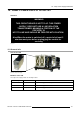


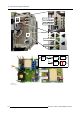
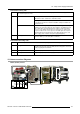
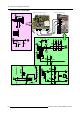

Table Of Contents
- toc
- 1. Safety
- 2. General Info SLM R12+ P
- 3. SLM R12+ P - Parts
- 4. SLM R12+ P - Location of the modules
- 5. SLM R12+ P - Location of the Fans
- 6. Interconnection diagram
- 7. IR Transmitter RC-5 Coded R763569
- 8. Local Keypad & LCD Display
- 9. Communication Module R763768
- 10. Serial Digital Input Module R7632485
- 11. Signal Input Selection R763850 & R763851
- 11.1 General Info
- 11.2 Block Diagram Signal Input Selection 1 & 2
- 11.3 Technical Description Input Selector 1 & 2
- 11.4 Power Supply
- 12. Digital Decoder R763826
- 13. Digital Inputs Backplane R763378
- 14. Power Distribution Backplane R764239
- 15. Lamp Power Supply R7633705
- 15.1 General Info
- 15.2 Technical Info
- 15.3 Interconnection Diagrams
- 15.4 Controls on Board
- 15.5 Technical Description LPS-X In/Out R7632113
- 15.5.1 General
- 15.5.2 Functions on the module:
- 15.5.3 EMC Filter - Rush-in Current Limit - Mains Rectifier.
- 15.5.4 On-board SMPS.
- 15.5.5 Secondary circuit of the LPS.
- 15.5.6 Measurement of the lamp voltage.
- 15.5.7 Lamp Current Measurement.
- 15.5.8 Boost up circuit.
- 15.5.9 Fan drive
- 15.5.10 LAMP_ON green LED indication.
- 15.6 Technical Description LPS-X Processing R7632105
- 15.7 Pin Assignment Connectors on Board
- 15.8 Adjustments on Board
- 16. Start Pulse Generator (SPG) R763512
- 17. Switch Mode Power Supply (SMPS) R764349
- 18. Temperature & Motor Control Module R764203
- 19. Formatter Interface Board (FIB) R764346
- 20. CPU Module R7638858
- 21. Pixel Map Processor Module R764115
- 22. Infra Red Receiver Module R763261
- 23. Ambient Temperature Sensor R762790
- 24. Projector Tilt Switch R764240
- 25. Light Output Sensor R763294
- 26. Lamp Info Module R763295
- 27. Maintenance
- 27.1 Lens Block
- 27.2 Cleaning/Replacement of the Dust Filters
- 27.3 Lamp Replacement
- 27.4 Re-convergence
- 27.4.1 Re-Convergence Kit
- 27.4.2 Preparation Projector for Re-Convergence
- 27.4.3 Re-convergence the Light Engine
- 27.5 Engine Replacement
- 27.5.1 Safety Instructions
- 27.5.2 Access to Image Processor Unit
- 27.5.3 Removing the Engine
- 27.5.3.1 Overview connections behind input box
- 27.5.3.2 Disconnecting the formatter and DMD connections
- 27.5.3.3 Removing the disconnected cables
- 27.5.3.4 Disconnect the lens sensor cable
- 27.5.3.5 Disconnect the shutter
- 27.5.3.6 Disconnect the lens holder ground leads
- 27.5.3.7 Disconnecting the engine fans
- 27.5.3.8 Removing the engine
- 27.5.4 Installing a new engine
- 27.5.5 Re-assembling the projector
- 27.6 Replacement of the Light Integration Rod
- 28. Upgrade with Air Filters
- 28.1 Air Filter Upgrade Kit for SLM R12+
- 28.2 Disassembling the projector for Cover replacement
- 28.3 Reassembling the projector with kit parts
- 28.3.1 Step by step actions
- 28.3.2 Reassembling Steps
- 28.3.2.1 Adaptation of the Safety cable tightening unit
- 28.3.2.2 Mounting the Bottom Cover with Air Filters
- 28.3.2.3 Mounting the Carrying handle fixation studs
- 28.3.2.4 Mounting the Carrying Handle
- 28.3.2.5 Mounting the removed Stacking interlocks
- 28.3.2.6 Mounting the IR Receiver Unit
- 28.3.2.7 Mounting the Bottom Cover with Air Filters
- 29. Overview of the Electrical Diagrams
- A. Specifications
15. Lamp Power Supply R7633705
Connectors Primary side
J609
Through this connector the module is connected with the SMPS of the projector. The SMPS is supplied with
the +380VM output of the PFC.
In standby mode: Rectified mains volatge
When PFC is active: +380V DC or +280V DC nominal
+380VM
The output is fused with F340 (1.25A) on the R7632103. The maximum
power that can be taken from that line is 250W in standby and 450W in the
operational mode.
V-SIN When the mains voltage disappears, this V_SIN also disappears but very
quickly, in fact, much faster than any other supply line. The SMPS gets from
this V_SIN a kind of warning that the mains supply is switched off and the
processor on the SMPS can take all necessary measures to switch off the
projector modules in the correct sequence. The DMD engine also requires a
signal that informs the formatter board on the abrupt disappearance of the
mains supply (short or relative short power supply interruptions).
J20/J21 MAINS _1/2 Mains_1 is the mains line input fused by a 20A (F100) located in the
connector. Mains_2 is the return (Max. is 274V AC.).
Connectors Secondary side
J620
As this is a looped connector, this connector has the same pin layout as the CONTROL_IN connector (J619).
NOT_ERROR MAINS This is an open collector output from the SMPS module. In the event of a fault
condition detected on the projector SMPS, this line is dropped to a low level,
hereby stopping the PFC and LPS.
J23
+LAMP_OUT Positive output (95Vdc max) for the lamp.
J24
- LAMP_OUT Negative output (return) for the lamp (approx. 0V)
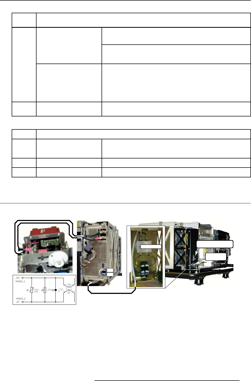
15.3 Interconnection Diagrams
Mains (Power) Circuit
Power Switch+
Magnetic circuit breaker
MAINS Input
MAINS Filter
J21
J20
Image 15-6
Mains power circuit
R5976820 SLM R12+ PERFORMER 08/03/2005 105