
Service manual
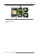
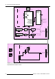
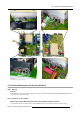
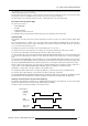
Table Of Contents
- toc
- 1. Safety
- 2. General Info SLM R12+ P
- 3. SLM R12+ P - Parts
- 4. SLM R12+ P - Location of the modules
- 5. SLM R12+ P - Location of the Fans
- 6. Interconnection diagram
- 7. IR Transmitter RC-5 Coded R763569
- 8. Local Keypad & LCD Display
- 9. Communication Module R763768
- 10. Serial Digital Input Module R7632485
- 11. Signal Input Selection R763850 & R763851
- 11.1 General Info
- 11.2 Block Diagram Signal Input Selection 1 & 2
- 11.3 Technical Description Input Selector 1 & 2
- 11.4 Power Supply
- 12. Digital Decoder R763826
- 13. Digital Inputs Backplane R763378
- 14. Power Distribution Backplane R764239
- 15. Lamp Power Supply R7633705
- 15.1 General Info
- 15.2 Technical Info
- 15.3 Interconnection Diagrams
- 15.4 Controls on Board
- 15.5 Technical Description LPS-X In/Out R7632113
- 15.5.1 General
- 15.5.2 Functions on the module:
- 15.5.3 EMC Filter - Rush-in Current Limit - Mains Rectifier.
- 15.5.4 On-board SMPS.
- 15.5.5 Secondary circuit of the LPS.
- 15.5.6 Measurement of the lamp voltage.
- 15.5.7 Lamp Current Measurement.
- 15.5.8 Boost up circuit.
- 15.5.9 Fan drive
- 15.5.10 LAMP_ON green LED indication.
- 15.6 Technical Description LPS-X Processing R7632105
- 15.7 Pin Assignment Connectors on Board
- 15.8 Adjustments on Board
- 16. Start Pulse Generator (SPG) R763512
- 17. Switch Mode Power Supply (SMPS) R764349
- 18. Temperature & Motor Control Module R764203
- 19. Formatter Interface Board (FIB) R764346
- 20. CPU Module R7638858
- 21. Pixel Map Processor Module R764115
- 22. Infra Red Receiver Module R763261
- 23. Ambient Temperature Sensor R762790
- 24. Projector Tilt Switch R764240
- 25. Light Output Sensor R763294
- 26. Lamp Info Module R763295
- 27. Maintenance
- 27.1 Lens Block
- 27.2 Cleaning/Replacement of the Dust Filters
- 27.3 Lamp Replacement
- 27.4 Re-convergence
- 27.4.1 Re-Convergence Kit
- 27.4.2 Preparation Projector for Re-Convergence
- 27.4.3 Re-convergence the Light Engine
- 27.5 Engine Replacement
- 27.5.1 Safety Instructions
- 27.5.2 Access to Image Processor Unit
- 27.5.3 Removing the Engine
- 27.5.3.1 Overview connections behind input box
- 27.5.3.2 Disconnecting the formatter and DMD connections
- 27.5.3.3 Removing the disconnected cables
- 27.5.3.4 Disconnect the lens sensor cable
- 27.5.3.5 Disconnect the shutter
- 27.5.3.6 Disconnect the lens holder ground leads
- 27.5.3.7 Disconnecting the engine fans
- 27.5.3.8 Removing the engine
- 27.5.4 Installing a new engine
- 27.5.5 Re-assembling the projector
- 27.6 Replacement of the Light Integration Rod
- 28. Upgrade with Air Filters
- 28.1 Air Filter Upgrade Kit for SLM R12+
- 28.2 Disassembling the projector for Cover replacement
- 28.3 Reassembling the projector with kit parts
- 28.3.1 Step by step actions
- 28.3.2 Reassembling Steps
- 28.3.2.1 Adaptation of the Safety cable tightening unit
- 28.3.2.2 Mounting the Bottom Cover with Air Filters
- 28.3.2.3 Mounting the Carrying handle fixation studs
- 28.3.2.4 Mounting the Carrying Handle
- 28.3.2.5 Mounting the removed Stacking interlocks
- 28.3.2.6 Mounting the IR Receiver Unit
- 28.3.2.7 Mounting the Bottom Cover with Air Filters
- 29. Overview of the Electrical Diagrams
- A. Specifications

15. Lamp Power Supply R7633705
Primary
Voltages
++15VM
• used as feedback information for stabilization of all output voltages.
• used in circuits with ”hot ground” on this board and via connector J603 on
the other board R7632103.
++24V
mainly used for supplying the two fans.
++15V
used on sheet 2/2 for several circuits, and also stabilized down to a stable
++5Vref.
Secondary
voltages
++110V
a floating voltage used to charge up the boostup capacitors (for the start up of
the lamp)
The SMPS starts up from 80Vac onwards. When the SMPS is in operation, the +380VM must drop first to 50V before the SMPS is
switched off. This accelerates the discharge of the electrolytic capacitors at the PFC output on the module R7632105.
15.5.5 Secondary circuit of the LPS.
Description
The separation / isolation between primary and secondary is realized with transformer T300. The relay RL2 , supplied from the line
TRAFO_RANGE, can change the ratio Npr
im / Nsec from LOW to HIGH. The ratio changes from 22/3 to 17/3.
Inside the transformer, a temperature sensing NTC resistor T300 provides an increasing voltage with temperature at the
TEMP_TRAFO line.
This information is handled by the microprocessor and the projector is shut down when the transformer reaches a predefined over-
temperature value, a value sto
red in eeprom on the R7632105.
The reverse voltage across the rectifier diodes may be maximum 300V. The most critical is the switching off time of the diodes.
Heavy ringing at turning off the diodes should be avoided.
A snubber 100E/1nF clamps too high ringing voltages.
The 100A coils L300 and L301 filter the HF components of the rectified current.
The capacitors C308 in paral
lel with a capacitor of 3000µF (C309+C310) (when the relay contacts are closed) filter the DC lamp
voltage.
At starting up, the lamp voltage is boosted up by the boost circuit around Q363 up to 105V and this high lamp voltage switches on
Q364. The relay RL3 opens its contacts and puts hereby a 1 Ohm in series with the electrolytic capacitors. From the moment the
lamp starts, the capacitors discharge through this 1 Ohm. The lamp voltage drops and the relay goes in rest position, shortening
the resistors. The electrolytic capacitors are now in parallel on the lamp electrodes.
15.5.6 Measurement of the lamp voltage.
Description
The lamp voltage at the secondary side must be measured and sent to the controller IC on the module R7632103.
The I330 buffers the voltage from the divider R334, R335.
The output VS (Voltage Sense) is led out to the other board via pin 6 of the CONTROL connector J603.
The voltage divisio
n is such that we obtain a ratio of 10 or, VS = 0.1V for 1V on the lamp.
Because the controller module on the R7632103 only can handle voltages up to 5V, the maximum lamp voltage that can be
measured is 50V.
15.5.7 Lamp Current Measurement.
Description
The lamp current is relatively high and is a DC current.
A trace on the pcb (printed circuit board) board serves as current sense resistor (R340). The sensed voltage is amplified with I340
and I341, and the
output voltage IS is adjusted with P340 to be equal at 0.04V for 1A in the output.
The NTC R346 compensates resistance variations in the pcb trace when the temperature varies.
The maximum lamp current that can be measured is 125A.
R5976820 SLM R12+ PERFORMER 08/03/2005
113