
Service manual
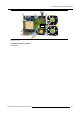
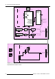
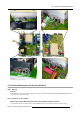
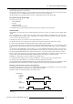
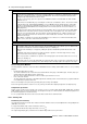
Table Of Contents
- toc
- 1. Safety
- 2. General Info SLM R12+ P
- 3. SLM R12+ P - Parts
- 4. SLM R12+ P - Location of the modules
- 5. SLM R12+ P - Location of the Fans
- 6. Interconnection diagram
- 7. IR Transmitter RC-5 Coded R763569
- 8. Local Keypad & LCD Display
- 9. Communication Module R763768
- 10. Serial Digital Input Module R7632485
- 11. Signal Input Selection R763850 & R763851
- 11.1 General Info
- 11.2 Block Diagram Signal Input Selection 1 & 2
- 11.3 Technical Description Input Selector 1 & 2
- 11.4 Power Supply
- 12. Digital Decoder R763826
- 13. Digital Inputs Backplane R763378
- 14. Power Distribution Backplane R764239
- 15. Lamp Power Supply R7633705
- 15.1 General Info
- 15.2 Technical Info
- 15.3 Interconnection Diagrams
- 15.4 Controls on Board
- 15.5 Technical Description LPS-X In/Out R7632113
- 15.5.1 General
- 15.5.2 Functions on the module:
- 15.5.3 EMC Filter - Rush-in Current Limit - Mains Rectifier.
- 15.5.4 On-board SMPS.
- 15.5.5 Secondary circuit of the LPS.
- 15.5.6 Measurement of the lamp voltage.
- 15.5.7 Lamp Current Measurement.
- 15.5.8 Boost up circuit.
- 15.5.9 Fan drive
- 15.5.10 LAMP_ON green LED indication.
- 15.6 Technical Description LPS-X Processing R7632105
- 15.7 Pin Assignment Connectors on Board
- 15.8 Adjustments on Board
- 16. Start Pulse Generator (SPG) R763512
- 17. Switch Mode Power Supply (SMPS) R764349
- 18. Temperature & Motor Control Module R764203
- 19. Formatter Interface Board (FIB) R764346
- 20. CPU Module R7638858
- 21. Pixel Map Processor Module R764115
- 22. Infra Red Receiver Module R763261
- 23. Ambient Temperature Sensor R762790
- 24. Projector Tilt Switch R764240
- 25. Light Output Sensor R763294
- 26. Lamp Info Module R763295
- 27. Maintenance
- 27.1 Lens Block
- 27.2 Cleaning/Replacement of the Dust Filters
- 27.3 Lamp Replacement
- 27.4 Re-convergence
- 27.4.1 Re-Convergence Kit
- 27.4.2 Preparation Projector for Re-Convergence
- 27.4.3 Re-convergence the Light Engine
- 27.5 Engine Replacement
- 27.5.1 Safety Instructions
- 27.5.2 Access to Image Processor Unit
- 27.5.3 Removing the Engine
- 27.5.3.1 Overview connections behind input box
- 27.5.3.2 Disconnecting the formatter and DMD connections
- 27.5.3.3 Removing the disconnected cables
- 27.5.3.4 Disconnect the lens sensor cable
- 27.5.3.5 Disconnect the shutter
- 27.5.3.6 Disconnect the lens holder ground leads
- 27.5.3.7 Disconnecting the engine fans
- 27.5.3.8 Removing the engine
- 27.5.4 Installing a new engine
- 27.5.5 Re-assembling the projector
- 27.6 Replacement of the Light Integration Rod
- 28. Upgrade with Air Filters
- 28.1 Air Filter Upgrade Kit for SLM R12+
- 28.2 Disassembling the projector for Cover replacement
- 28.3 Reassembling the projector with kit parts
- 28.3.1 Step by step actions
- 28.3.2 Reassembling Steps
- 28.3.2.1 Adaptation of the Safety cable tightening unit
- 28.3.2.2 Mounting the Bottom Cover with Air Filters
- 28.3.2.3 Mounting the Carrying handle fixation studs
- 28.3.2.4 Mounting the Carrying Handle
- 28.3.2.5 Mounting the removed Stacking interlocks
- 28.3.2.6 Mounting the IR Receiver Unit
- 28.3.2.7 Mounting the Bottom Cover with Air Filters
- 29. Overview of the Electrical Diagrams
- A. Specifications

15. Lamp Power Supply R7633705
15.5.8 Boost up circuit.
Description
The ++110V , ++110RET voltage is a floating supply delivered by the on-board SMPS. When the opto-coupler is switched ON by
the processor (BOOST_ON) The ++110V voltage charges up the capacitors C309 /C310 via the current source Q363. This current
is determined by the zener voltage of Z360, the threshold of Q363 and the source resistors R373+R374.
As soon the zeners Z361 to Z363 start conducting, the transistor Q361 which drives Q362 reduces the current of the current source.
A stable situation is reached until the processor turns off the opto-coupler and consequently also the MOSFET.
During that stable situation, the voltage across the lamp is roughly the sum of the three zeners Z361+Z362+Z363, this is 93V.
15.5.9 Fan drive
Description
Because the fans only can start when the boost circuit is switched off and have to continue cooling after the LPS is turned off, the
drive is done by the processor with the FAN_SPD line.
The two fans are connected in parallel and pulse width modulated with Q381. Because the SMPS cannot supply the fans and the
boost circuit simultaneously (this would require too much power from it), the fans only are started when the boost circuit is turned off.
The time the fans keep blowing after switching off, is programmable.
The signal FAN_OK goes low when either of the fans does not rotate.
15.5.10LAMP_ON green LED indication.
Description
The secondary transformer outputs SEC1 and SEC2 of T300 are rectified with D330 and D33
1, and applied to the base of Q330.
The LED turns on from a lamp voltage of 12V onwards.
15.6 Technical Description LPS-X Processing R7632105
15.6.1 General
Preview
This module is part of the complete LPS and performs following functions :
• A microcontroller with I2C interface an peripheral circuits for controlling and monitoring the LPS module
• PFC Power factor Corrector.
• Primary of the LPS and a part of the feedback circuits.
15.6.2 Controller circuits and controller interface circuits:
On sheet 1/5
The connector J619 (CONTROL IN) realizes the connection with the SMPS and carries the I²C bus lines SDA and SCL.
J620 is the CONTROL OUT connector (in parallel or ‘looped through’) to the second or third LPS unit, if present.
The ++5V supply voltage for the secondary circuits (with cold chassis ground) comes from the SMPS via J619.
A local ++15V and -13V are generated with the circuit around I150.
The SCL and SDA lines, and the two address lines from J619 are directly connected to the controller I214 on sheet 2/5.3
On sheet 2/5 and sheet 3/5
The controller I214 has following inputs & outputs:
8 Digital Inputs
NOT_EXT_ERROR This is an input from the SMPS module in the projector; a low level indicates an
error, and shuts down LPS and PFC.
ADR_0
First address line from J619/J620.
ADR_1
Second address line from J619/J620.
114 R5976820 SLM R12+ PERFORMER 08/03/2005