
Service manual
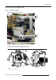
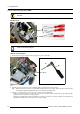
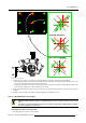

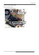
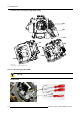
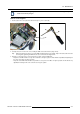

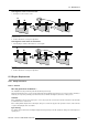
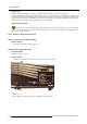
Table Of Contents
- toc
- 1. Safety
- 2. General Info SLM R12+ P
- 3. SLM R12+ P - Parts
- 4. SLM R12+ P - Location of the modules
- 5. SLM R12+ P - Location of the Fans
- 6. Interconnection diagram
- 7. IR Transmitter RC-5 Coded R763569
- 8. Local Keypad & LCD Display
- 9. Communication Module R763768
- 10. Serial Digital Input Module R7632485
- 11. Signal Input Selection R763850 & R763851
- 11.1 General Info
- 11.2 Block Diagram Signal Input Selection 1 & 2
- 11.3 Technical Description Input Selector 1 & 2
- 11.4 Power Supply
- 12. Digital Decoder R763826
- 13. Digital Inputs Backplane R763378
- 14. Power Distribution Backplane R764239
- 15. Lamp Power Supply R7633705
- 15.1 General Info
- 15.2 Technical Info
- 15.3 Interconnection Diagrams
- 15.4 Controls on Board
- 15.5 Technical Description LPS-X In/Out R7632113
- 15.5.1 General
- 15.5.2 Functions on the module:
- 15.5.3 EMC Filter - Rush-in Current Limit - Mains Rectifier.
- 15.5.4 On-board SMPS.
- 15.5.5 Secondary circuit of the LPS.
- 15.5.6 Measurement of the lamp voltage.
- 15.5.7 Lamp Current Measurement.
- 15.5.8 Boost up circuit.
- 15.5.9 Fan drive
- 15.5.10 LAMP_ON green LED indication.
- 15.6 Technical Description LPS-X Processing R7632105
- 15.7 Pin Assignment Connectors on Board
- 15.8 Adjustments on Board
- 16. Start Pulse Generator (SPG) R763512
- 17. Switch Mode Power Supply (SMPS) R764349
- 18. Temperature & Motor Control Module R764203
- 19. Formatter Interface Board (FIB) R764346
- 20. CPU Module R7638858
- 21. Pixel Map Processor Module R764115
- 22. Infra Red Receiver Module R763261
- 23. Ambient Temperature Sensor R762790
- 24. Projector Tilt Switch R764240
- 25. Light Output Sensor R763294
- 26. Lamp Info Module R763295
- 27. Maintenance
- 27.1 Lens Block
- 27.2 Cleaning/Replacement of the Dust Filters
- 27.3 Lamp Replacement
- 27.4 Re-convergence
- 27.4.1 Re-Convergence Kit
- 27.4.2 Preparation Projector for Re-Convergence
- 27.4.3 Re-convergence the Light Engine
- 27.5 Engine Replacement
- 27.5.1 Safety Instructions
- 27.5.2 Access to Image Processor Unit
- 27.5.3 Removing the Engine
- 27.5.3.1 Overview connections behind input box
- 27.5.3.2 Disconnecting the formatter and DMD connections
- 27.5.3.3 Removing the disconnected cables
- 27.5.3.4 Disconnect the lens sensor cable
- 27.5.3.5 Disconnect the shutter
- 27.5.3.6 Disconnect the lens holder ground leads
- 27.5.3.7 Disconnecting the engine fans
- 27.5.3.8 Removing the engine
- 27.5.4 Installing a new engine
- 27.5.5 Re-assembling the projector
- 27.6 Replacement of the Light Integration Rod
- 28. Upgrade with Air Filters
- 28.1 Air Filter Upgrade Kit for SLM R12+
- 28.2 Disassembling the projector for Cover replacement
- 28.3 Reassembling the projector with kit parts
- 28.3.1 Step by step actions
- 28.3.2 Reassembling Steps
- 28.3.2.1 Adaptation of the Safety cable tightening unit
- 28.3.2.2 Mounting the Bottom Cover with Air Filters
- 28.3.2.3 Mounting the Carrying handle fixation studs
- 28.3.2.4 Mounting the Carrying Handle
- 28.3.2.5 Mounting the removed Stacking interlocks
- 28.3.2.6 Mounting the IR Receiver Unit
- 28.3.2.7 Mounting the Bottom Cover with Air Filters
- 29. Overview of the Electrical Diagrams
- A. Specifications
27. Maintenance
R
B
G
Ba2
Bb2
Ba3
Bb3
Ba1
Bb1
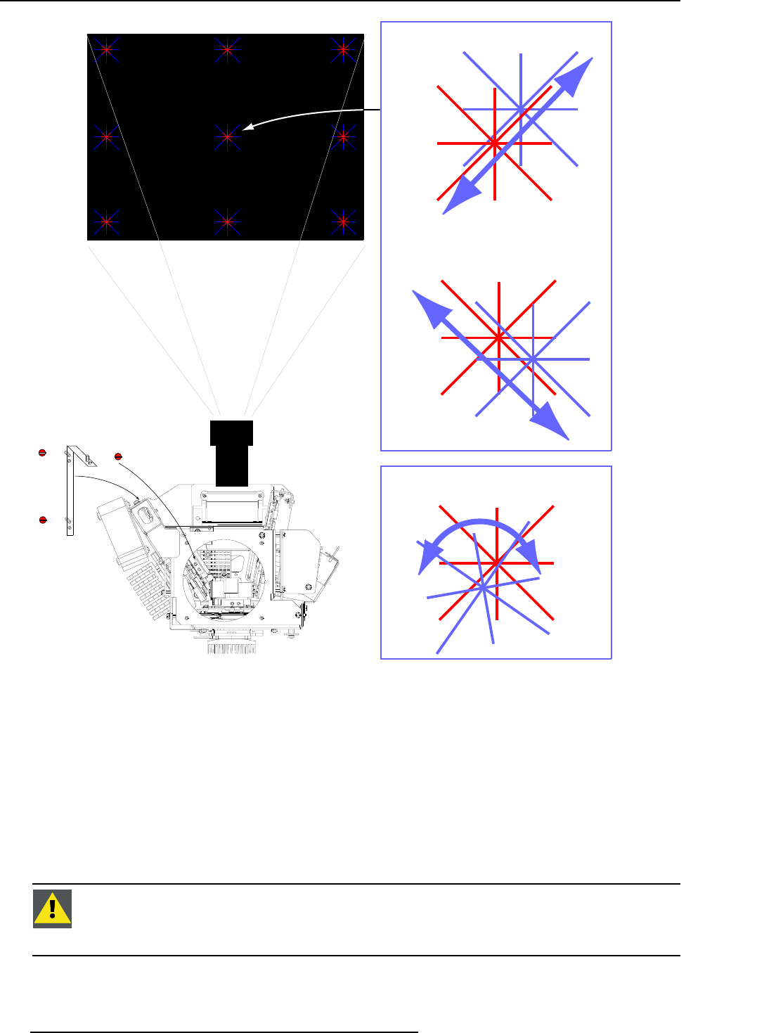
Bb1 adjustment
Bb2+Bb3 adjustment
Bb2 or Bb3 adjustment
Bb3: top image
Bb2: bottom image
Image 27-63
Blue convergence adjustment
4. Continue with re-converging the center at the Top and the Bottom of the image as follows (using tool R847204):
- Adjust the control Bb3 for coincidence of the diagonal Blue line of the Blue convergence pattern with the Red line of the Red
convergence pattern in the center at the top of the image.
- Adjust the control Bb2 for coincidence of the diagonal Blue line of the Blue convergence pattern with the Red line of the Red
convergence pattern in the center at the bottom of the image
5. Because the different adjust
ments interact, step 3 and 4 have to be repeated until full coincidence of both convergence pattern
is obtained.
6. Carefully secure the position of the DMD assembly by tightening the 4 lock-down screws.
27.4.3.3.3 Readjustment of the plungers
CAUTION: Do NOT adjust the plungers on the DMD assembly, if small convergence drifts have to be corrected
only.
For extreme convergence adjustments, possible in case after the replacement of a DMD assembly, a readjust-
ment of the plungers can
be necessary.
216 R5976820 SLM R12+ PERFORMER 08/03/2005