
Service manual
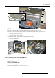
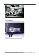
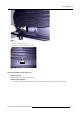
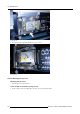
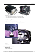
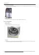
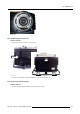
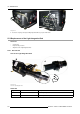
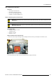
Table Of Contents
- toc
- 1. Safety
- 2. General Info SLM R12+ P
- 3. SLM R12+ P - Parts
- 4. SLM R12+ P - Location of the modules
- 5. SLM R12+ P - Location of the Fans
- 6. Interconnection diagram
- 7. IR Transmitter RC-5 Coded R763569
- 8. Local Keypad & LCD Display
- 9. Communication Module R763768
- 10. Serial Digital Input Module R7632485
- 11. Signal Input Selection R763850 & R763851
- 11.1 General Info
- 11.2 Block Diagram Signal Input Selection 1 & 2
- 11.3 Technical Description Input Selector 1 & 2
- 11.4 Power Supply
- 12. Digital Decoder R763826
- 13. Digital Inputs Backplane R763378
- 14. Power Distribution Backplane R764239
- 15. Lamp Power Supply R7633705
- 15.1 General Info
- 15.2 Technical Info
- 15.3 Interconnection Diagrams
- 15.4 Controls on Board
- 15.5 Technical Description LPS-X In/Out R7632113
- 15.5.1 General
- 15.5.2 Functions on the module:
- 15.5.3 EMC Filter - Rush-in Current Limit - Mains Rectifier.
- 15.5.4 On-board SMPS.
- 15.5.5 Secondary circuit of the LPS.
- 15.5.6 Measurement of the lamp voltage.
- 15.5.7 Lamp Current Measurement.
- 15.5.8 Boost up circuit.
- 15.5.9 Fan drive
- 15.5.10 LAMP_ON green LED indication.
- 15.6 Technical Description LPS-X Processing R7632105
- 15.7 Pin Assignment Connectors on Board
- 15.8 Adjustments on Board
- 16. Start Pulse Generator (SPG) R763512
- 17. Switch Mode Power Supply (SMPS) R764349
- 18. Temperature & Motor Control Module R764203
- 19. Formatter Interface Board (FIB) R764346
- 20. CPU Module R7638858
- 21. Pixel Map Processor Module R764115
- 22. Infra Red Receiver Module R763261
- 23. Ambient Temperature Sensor R762790
- 24. Projector Tilt Switch R764240
- 25. Light Output Sensor R763294
- 26. Lamp Info Module R763295
- 27. Maintenance
- 27.1 Lens Block
- 27.2 Cleaning/Replacement of the Dust Filters
- 27.3 Lamp Replacement
- 27.4 Re-convergence
- 27.4.1 Re-Convergence Kit
- 27.4.2 Preparation Projector for Re-Convergence
- 27.4.3 Re-convergence the Light Engine
- 27.5 Engine Replacement
- 27.5.1 Safety Instructions
- 27.5.2 Access to Image Processor Unit
- 27.5.3 Removing the Engine
- 27.5.3.1 Overview connections behind input box
- 27.5.3.2 Disconnecting the formatter and DMD connections
- 27.5.3.3 Removing the disconnected cables
- 27.5.3.4 Disconnect the lens sensor cable
- 27.5.3.5 Disconnect the shutter
- 27.5.3.6 Disconnect the lens holder ground leads
- 27.5.3.7 Disconnecting the engine fans
- 27.5.3.8 Removing the engine
- 27.5.4 Installing a new engine
- 27.5.5 Re-assembling the projector
- 27.6 Replacement of the Light Integration Rod
- 28. Upgrade with Air Filters
- 28.1 Air Filter Upgrade Kit for SLM R12+
- 28.2 Disassembling the projector for Cover replacement
- 28.3 Reassembling the projector with kit parts
- 28.3.1 Step by step actions
- 28.3.2 Reassembling Steps
- 28.3.2.1 Adaptation of the Safety cable tightening unit
- 28.3.2.2 Mounting the Bottom Cover with Air Filters
- 28.3.2.3 Mounting the Carrying handle fixation studs
- 28.3.2.4 Mounting the Carrying Handle
- 28.3.2.5 Mounting the removed Stacking interlocks
- 28.3.2.6 Mounting the IR Receiver Unit
- 28.3.2.7 Mounting the Bottom Cover with Air Filters
- 29. Overview of the Electrical Diagrams
- A. Specifications
27. Maintenance
B
A
B
Image 27-121
2. Secure the 4 spring screws (B), holding Input Panel Box to projector main frame.
27.6 Replacement of the Light Integration Rod
Overview
• General Info
• Replacement procedure
• Alignment of the Light Integration Rod
27.6.1 General Info
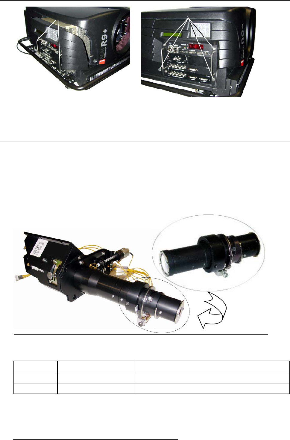
View of the Light Integration Rod
A
B
Image 27-122
View of the Light Integration Rod
Order Info
Image Ref. Order No.
Description
A R849700 DLP
TM
Light Integration Rod
B R840546
DLP
TM
Light Unit Complete
246 R5976820 SLM R12+ PERFORMER 08/03/2005