_äÉåÇmolJff rëÉêÛë=dìáÇÉ • • Manual # 26-0507000-00 Revision A
_äÉåÇmolJff=√=rëÉêÛë=dìáÇÉ `çéóêáÖÜí © Barco, Inc. August 7, 2006 All rights reserved. No part of this document may be copied, reproduced or translated. It shall not otherwise be recorded, transmitted or stored in a retrieval system without the prior written consent of Barco. kçíáÅÉ Barco provides this manual “as is” without warranty of any kind, either expressed or implied, including but not limited to the implied warranties or merchantability and fitness for a particular purpose.
agreed upon in the contract, all guarantee claims of the purchaser will be rendered invalid. Not included in the guarantee coverage are system failures which are attributed to programs or special electronic circuitry provided by the purchaser, e.g. interfaces. Normal wear as well as normal maintenance are not subject to the guarantee provided by Barco either. The environmental conditions as well as the servicing and maintenance regulations specified in this manual must be complied with by the customer.
léÉê~íçêë=p~ÑÉíó=pìãã~êó The general safety information in this summary is for operating personnel. aç=kçí=oÉãçîÉ=`çîÉêë=çê=m~åÉäë There are no user-serviceable parts within the unit. Removal of the top cover will expose dangerous voltages. To avoid personal injury, do not remove the top cover. Do not operate the unit without the cover installed.
qÉêãë=få=qÜáë=j~åì~ä=~åÇ=bèìáéãÉåí=j~êâáåÖ= t^okfkd Highlights an operating procedure, practice, condition, statement, etc., which, if not strictly observed, could result in injury to or death of personnel. Note Highlights an essential operating procedure, condition or statement. `^rqflk The exclamation point within an equilateral triangle is intended to alert the user to the presence of important operating and maintenance (servicing) instructions in the literature accompanying the appliance.
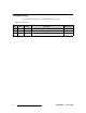
`Ü~åÖÉ=eáëíçêó The table below lists the changes to the BlendPRO-II User’s Guide. Table 0-1. Change History Rev A 6 Date 8/7/06 ECO # 1674 Description BlendPRO-II User’s Guide Approved By M.
q~ÄäÉ=çÑ=`çåíÉåíë `Ü~éíÉê=N fåíêçÇìÅíáçå =K=K=K=K=K=K=K=K=K=K=K=K=K=K=K=K=K=K=K=K=K=K=K=K=K=K=K=K=K=K=K=K=K=K=K=K=K=K=K=K=K=K= V In This Chapter . . . . . . . . . . . . . . . . . . . . . . . . . . . . . . . . . . . . . . . . . . . . . . . . . 9 Chapter Structure . . . . . . . . . . . . . . . . . . . . . . . . . . . . . . . . . . . . . . . . . . . . . . 10 How to Use This Guide. . . . . . . . . . . . . . . . . . . . . . . . . . . . . . . . . . . . . . . . . . 11 Navigating . . . . . . . . . . . . . . . . .
Table of Contents ^ééÉåÇáñ=^= péÉÅáÑáÅ~íáçåëK=K=K=K=K=K=K=K=K=K=K=K=K=K=K=K=K=K=K=K=K=K=K=K=K=K=K=K=K=K=K=K=K=K=K=K=K=K=K=K=PP In This Appendix. . . . . . . . . . . . . . . . . . . . . . . . . . . . . . . . . . . . . . . . . . . . . . . Input Specifications . . . . . . . . . . . . . . . . . . . . . . . . . . . . . . . . . . . . . . . . . . . . Output Specifications . . . . . . . . . . . . . . . . . . . . . . . . . . . . . . . . . . . . . . . . . . . User Control Specifications . . . . . . . . . . . . . .
NK==fåíêçÇìÅíáçå få=qÜáë=`Ü~éíÉê This chapter is designed to introduce you to the BlendPRO-II User’s Guide.
NK==fåíêçÇìÅíáçå Chapter Structure `Ü~éíÉê=píêìÅíìêÉ The following chapters provide instructions for all aspects of BlendPRO-II operations: 10 • Chapter 1, “Introduction” provides a system overview, a list of features, and a system connectivity diagram. • Chapter 2, “Hardware Orientation” on page 15 provides detailed diagrams of the system’s front and rear panels. • Chapter 3, “Installation” on page 21 provides comprehensive system installation instructions.
NK==fåíêçÇìÅíáçå How to Use This Guide eçï=íç=rëÉ=qÜáë=dìáÇÉ Following are important tips for streamlining your use of this User’s Guide in its electronic “PDF” form. k~îáÖ~íáåÖ Use Acrobat Reader’s “bookmarks” to navigate to the desired location. All chapter files have the same bookmark structure for instant navigation to any section. Please note: • • Extensive hyperlinks are provided within the chapters.
NK==fåíêçÇìÅíáçå About the BlendPRO-II ^Äçìí=íÜÉ=_äÉåÇmolJff The BlendPRO-II is a “presentation” system component that allows standard highresolution images (as generated by multiple ScreenPro-II units) to be displayed in a multiprojector widescreen format. The system completely eliminates the need to “pre-overlap” source material during the content creation phase of your presentation.
NK==fåíêçÇìÅíáçå Features cÉ~íìêÉë The BlendPRO-II system includes the following advanced features: • • • • • • • • Blending of up to four ScreenPro-II units. User programmable data doubling, edge-feathering, and output gamma. Simultaneous digital and analog outputs. Real-time command synchronization between all connected ScreenPRO-II units. Separate Genlock and Widescreen Lock connections (BNC). Progressive video format support. Low video delay, less than 6 lines. Integral test pattern generator.
NK==fåíêçÇìÅíáçå Connectivity Diagram `çååÉÅíáîáíó=aá~Öê~ã The figure below illustrates a sample connectivity diagram: X4 Widescreen Blend Preview 1 Preview 2 Preview 3 Preview 4 Program 1 Program 2 Analog Program 3 Program 4 Analog ScreenPRO-II ID #1 ScreenPRO-II ID #2 DVI Out or Analog Out BlendPRO-II DVI In Widescreen Lock (Required) Genlock In (Optional) ScreenPRO-II Controller ScreenPRO-II ID #3 ScreenPRO-II ID #4 Switch Ethernet Figure 1-1.
OK==e~êÇï~êÉ=lêáÉåí~íáçå få=qÜáë=`Ü~éíÉê This chapter provides detailed diagrams of the system’s front and rear panels.
2. Hardware Orientation BlendPRO-II Front Panel _äÉåÇmolJff=cêçåí=m~åÉä The figure below illustrates the BlendPRO-II front panel: Visibly yours BLENDPRO II Figure 2-1. BlendPRO-II Front Panel There are no user controls on the front panel of the BlendPRO-II chassis. All operating procedures are performed through the ScreenPRO-II Controller. Refer to Chapter 4, “Operation” on page 29 for additional details.
2. Hardware Orientation BlendPRO-II Rear Panel _äÉåÇmolJff=oÉ~ê=m~åÉä The figure below illustrates the BlendPRO-II rear panel: 1 2 3 4 SERIAL GENLOCK IN WIDESCREEN LOCK OUT OUTPUTS 1 2 3 4 1 2 3 4 ETHERNET INPUTS 1 2 3 4 100-240 V 50-60 Hz 2.3 A 5 6 7 Figure 2-1.
2. Hardware Orientation BlendPRO-II Rear Panel 3) Serial Port One 9-pin D connector is provided for RS-232 serial communications with BlendPRO-II, typically for diagnostic purposes. The port is configured as a DCE, 115K Baud, 8 data bit, 1 stop bit, and no parity bits. The port can be connected to a standard PC serial port with a straight through DB-9 to DB-9 cable. In Appendix A, refer to the “Serial Connector” section on page 40 for pinouts.
2. Hardware Orientation BlendPRO-II Rear Panel 6) Outputs Section The figure below illustrates the Outputs Section: OUTPUTS 1 2 3 4 1 2 3 4 Figure 2-3. BlendPRO-II Outputs Section The Outputs Section includes four digital and four analog outputs: ~ DVI — the four DVI digital outputs are per DDWG 1.0 specifications. All four are DVI-D (digital, single link, receptacle) using DVI-I connectors. The DVI outputs are of the same resolution as the inputs.
2.
PK==fåëí~ää~íáçå få=qÜáë=`Ü~éíÉê This chapter provides detailed instructions for installing the BlendPRO-II hardware.
3. Installation Safety Precautions p~ÑÉíó=mêÉÅ~ìíáçåë= For all BlendPRO-II installation procedures, observe the following important safety and handling rules to avoid damage to yourself and the equipment: • To protect users from electric shock, ensure that the power supplies for each unit connect to earth via the ground wire provided in the AC power Cord. • The AC Socket-outlet should be installed near the equipment and be easily accessible.
3. Installation Rack-Mount Installation o~ÅâJjçìåí=fåëí~ää~íáçå BlendPRO-II units are designed to be rack mounted and are supplied with front rack-mount hardware. Please note the following important points: • Rear rack-mount brackets are available as a kit, and are recommended for use when units are mounted in transit cases. • When rack mounting the unit, remember that the maximum ambient operating temperature for the unit is 40 degrees C.
3. Installation Power Installation mçïÉê=`çêÇLiáåÉ=sçäí~ÖÉ=pÉäÉÅíáçå BlendPRO-II is rated to operate with the following supplies: • • Input Power: 100-240 VAC, 47-63 Hz Power Consumption: 80 watts maximum BlendPRO-II performs line voltage selection automatically, and no user controls are required. The AC power cords must be accessible so that they can be removed during field servicing.
3. Installation Signal Installation páÖå~ä=fåëí~ää~íáçå The figure below illustrates a sample BlendPRO-II system, which uses the maximum four ScreenPRO-II units. Use this figure for reference during the signal installation process. If required, refer to the “BlendPRO-II Rear Panel” section on page 17 in Chapter 2 for details on all rear panel connectors.
3. Installation Signal Installation without IP connections to the outside world. Use standard Ethernet cables in conjunction with an Ethernet switch. 3. Connect a DVI output from each ScreenPRO-II unit (up to the maximum of 4) to the DVI inputs on BlendPRO-II. 4. Connect the DVI or analog outputs from BlendPRO-II to the inputs of your selected projectors (up to the maximum of 4).
3. Installation Signal Installation c. (If your system includes three ScreenPRO-IIs) — Connect the second ScreenPRO-II’s GENLOCK LOOP connector to the GENLOCK IN connector on the ScreenPRO-II with the next highest numbered ID. d. (If your system includes four ScreenPRO-IIs) — Connect the third ScreenPRO-II’s GENLOCK LOOP connector to the GENLOCK IN connector on the ScreenPRO-II unit with the highest numbered ID. e.
3. Installation Format Connection Table cçêã~í=`çååÉÅíáçå=q~ÄäÉ Use the following table to connect BlendPRO-II’s analog RGB output to various analog projector inputs (3 wire, 4 wire and 5 wire). Using a customer supplied VGA to 5 x BNC breakout cable, multiple combinations are possible. Cells with checks denote the connections required for the indicated format. Note For RGB with H and V sync, use the VGA connector directly. Table 3-2.
QK==léÉê~íáçå få=qÜáë=`Ü~éíÉê This chapter provides detailed operating instructions for the BlendPRO-II.
4. Operation Control Overview `çåíêçä=lîÉêîáÉï All BlendPRO-II setup and operating procedures are performed through the ScreenPRO-II Controller. There are no user controls on the BlendPRO-II unit itself. Important 30 Refer to the “ScreenPRO-II Controller User’s Guide” for complete setup and operating procedures.
RK==réÖê~ÇáåÖ=pçÑíï~êÉ få=qÜáë=`Ü~éíÉê This chapter provides instructions for upgrading BlendPRO-II system software.
5. Upgrading Software Software Upgrade Overview pçÑíï~êÉ=réÖê~ÇÉ=lîÉêîáÉï All software upgrade procedures are performed through the ScreenPRO-II Controller. There are no user controls provided on the BlendPRO-II unit itself. Please note: • Code compatibility — when the ScreenPRO-II Controller connects to the individual ScreenPRO-II units and to BlendPRO-II, it automatically checks the compatibility of the code versions.
^K==péÉÅáÑáÅ~íáçåë få=qÜáë=^ééÉåÇáñ This appendix provides detailed technical specifications for the BlendPRO-II.
^K==péÉÅáÑáÅ~íáçåë Input Specifications fåéìí=péÉÅáÑáÅ~íáçåë= The table below lists BlendPRO-II input specifications. Table A-1. BlendPRO-II Input Specifications Parameter Detail DVI Inputs 1 - 4 Genlock Input Specification Connector (4) DVI-D connectors (digital, single link, receptacle), each input per DDWG 1.0 specifications. Video Progressive RGB Clock Speed / Resolution 25 - 162MHz (1600x1200x60Hz) Lock All inputs must be of the same resolution and H/V locked.
^K==péÉÅáÑáÅ~íáçåë User Control Specifications rëÉê=`çåíêçä=péÉÅáÑáÅ~íáçåë The table below lists BlendPRO-II user control specifications. Table A-3. BlendPRO-II User Control Specifications Parameter Detail User Control Specification Operations No local controls provided. Setup All setup functions performed from ScreenPRO-II Controller. Remote control All control functions performed from ScreenPRO-II Controller.
^K==péÉÅáÑáÅ~íáçåë Communications Specifications `çããìåáÅ~íáçåë=péÉÅáÑáÅ~íáçåë= The table below lists BlendPRO-II communications specifications. Table A-5. BlendPRO-II Communications Specifications Parameter Communications Detail Specification RS-232 DB-9 Female, DCE, 115k Baud Ethernet RJ-45, 10/100 Mbps Autosense ^ÖÉåÅó=péÉÅáÑáÅ~íáçåë= The table below lists BlendPRO-II agency specifications. Table A-6.
^K==péÉÅáÑáÅ~íáçåë Pinouts máåçìíë= The following topics are discussed in this section: • • • • Analog 15-pin D Connector DVI Connector Pinouts Ethernet Connector Serial Connector ^å~äçÖ=NRJéáå=a=`çååÉÅíçê The figure below illustrates the analog 15-pin D connector: 5 1 10 6 15 11 Figure A-1. Analog 15-pin D Connector, chassis view The table below lists Analog 15-pin D connector pinouts. Table A-7.
^K==péÉÅáÑáÅ~íáçåë Pinouts asf=`çååÉÅíçê=máåçìíë The figure below illustrates the DVI-I connector: 1 8 17 24 9 Figure A-2. DVI-I Connector The table below lists DVI-I Connector pinouts. Please note: • • T.M.D.S = Transition Minimized Differential Signal DDC = Display Data Channel Table A-8. DVI-I Connector Pinouts Pin Signal Signal 1 T.M.D.S. Data 2- 13 T.M.D.S. Data 3+ 2 T.M.D.S. Data 2+ 14 +5V Power 3 T.M.D.S. Data 2/4 Shield 15 ground (for +5V) 4 T.M.D.S.
^K==péÉÅáÑáÅ~íáçåë Pinouts bíÜÉêåÉí=`çååÉÅíçê The figure below illustrates the Ethernet connector: 1 8 Figure A-3. Ethernet Connector The table below lists Ethernet connector pinouts. Table A-9.
^K==péÉÅáÑáÅ~íáçåë Pinouts pÉêá~ä=`çååÉÅíçê The figure below illustrates the Serial connector: 5 1 9 6 Figure A-4. Serial Connector The table below lists Serial connector pinouts. Table A-10.
_K==`çåí~Åí=fåÑçêã~íáçå få=qÜáë=^ééÉåÇáñ The following topics are discussed in this Appendix: • • • Warranty Return Material Authorization (RMA) Contact Information t~êê~åíó All video products are designed and tested to the highest quality standards and are backed by a full 3-year parts and labor warranty. Warranties are effective upon delivery date to customer and are non-transferable. Barco warranties are only valid to the original purchaser/owner.
_K==`çåí~Åí=fåÑçêã~íáçå Contact Information `çåí~Åí=fåÑçêã~íáçå Barco Media and Entertainment 11101 Trade Center Drive Rancho Cordova, California 95670 USA • • • Phone: (916) 859-2500 Fax: (916) 859-2515 Websites: ~ ~ www.folsom.com www.events.barco.com Sales Contact Information • • • Direct: (916) 859-2505 Toll Free: (888) 414-7226 E-mail: folsomsales@barco.com Barco N.V. Noordlaan 5 8520 Kuurne BELGIUM • • • Phone: +32 56.36.82.11 Fax: +32 56.35.16.51 Website: www.barco.
fåÇÉñ ^ ` About BlendPRO-II . . . . . . . . . . . . . . . . . . . . .12 AC connector . . . . . . . . . . . . . . . . . . . . . . . . .18 power cords . . . . . . . . . . . . . . . . . . . . . . .24 Acrobat usage . . . . . . . . . . . . . . . . . . . . . . . . . 11 navigating and searching . . . . . . . . . . . . . 11 Adapter information . . . . . . . . . . . . . . . . . . . . .22 Address, company . . . . . . . . . . . . . . . . . . . . . . .3 Agency specifications . . . . . . . . . . . . . . . . . . .
Index c Introduction to BlendPRO-II . . . . . . . . . . . . . . . .9 FCC statement . . . . . . . . . . . . . . . . . . . . . . . . . .2 Features, BlendPRO-II . . . . . . . . . . . . . . . . . .13 Front panel connectors . . . . . . . . . . . . . . . . . .16 i Line voltage selection . . . . . . . . . . . . . . . . . . .24 d k Genlock termination . . . . . . . . . . . . . . . . . . . . .27 Guarantee and compensation . . . . . . . . . . . . . .2 Notice e l Hardware installation . . . . . . . . . . .
Index Sales contact information . . . . . . . . . . . . . . . .42 Serial connector pinouts . . . . . . . . . . . . . . . . . . .40 port . . . . . . . . . . . . . . . . . . . . . . . . . . . . . .18 Signal installation . . . . . . . . . . . . . . . . . . . . . . .25 Site preparation . . . . . . . . . . . . . . . . . . . . . . . .22 Software upgrade overview . . . . . . . . . . . . . . . . . . .32 upgrading . . . . . . . . . . . . . . . . . . . . . . . . .31 Specifications . . . . . . . . . . . . . . . . . .
Index 46 BlendPRO-II • User’s Guide