HOME CINEMA BARCO CINE7 R9010040 R9010050 OWNERS MANUAL 26022003 R5976584/00
Barco nv Home Cinema Noordlaan 5, B-8520 Kuurne Phone: +32 56.36.84.30 Fax: +32 56.36.88.62 E-mail: salesassistantht.bci@barco.com Visit us at the web: www.homecinema.barco.
Changes Barco provides this manual “as is” without warranty of any kind, either expressed or implied, including but not limited to the implied warranties or merchantability and fitness for a particular purpose. Barco may make improvements and/or changes to the product(s) and/or the program(s) described in this publication at any time without notice. This publication could contain technical inaccuracies or typographical errors.
Table of contents TABLE OF CONTENTS 1. Safety Instructions .. .. .. .. .. .. .. .. .. .. .. .. .. .. .. .. .. .. .. .. .. .. .. .. .. .. .. .. .. .. .. .. .. .. .. .. .. .. .. .. .. .. .. .. .. .. .. .. .. 5 1.1 Safety Instructions . . . . . . . . . . . . . . . . . . . . . . . . . . . . . . . . . . . . . . . . . . . . . . . . . . . . . . . . . . . . . . . . . . . . . . . . . . . . . . . . . . . . . . . . . . . . . . . . . . . . . . . . . . . . . . . . . . . . . . 5 2. AC Power . .. .. .. .. .. .. .. .. ..
Table of contents 8.5 Picture Tuning . . . . . . . . . . . . . . . . . . . . . . . . . . . . . . . . . . . . . . . . . . . . . . . . . . . . . . . . . . . . . . . . . . . . . . . . . . . . . . . . . . . . . . . . . . . . . . . . . . . . . . . . . . . . . . . . . . . . . . . . . . 52 8.5.1 Starting up Picture Tuning . . . . . . . . . . . . . . . . . . . . . . . . . . . . . . . . . . . . . . . . . . . . . . . . . . . . . . . . . . . . . . . . . . . . . . . . . . . . . . . . . . . . . . . . . . . . . . . . . .
Table of contents 10.Programmable Function Keys .. .. .. .. .. .. .. .. .. .. .. .. .. .. .. .. .. .. .. .. .. .. .. .. .. .. .. .. .. .. .. .. .. .. .. .. .. .. .. .. .. . 99 10.1Programming a Function Keys . . . . . . . . . . . . . . . . . . . . . . . . . . . . . . . . . . . . . . . . . . . . . . . . . . . . . . . . . . . . . . . . . . . . . . . . . . . . . . . . . . . . . . . . . . . . . . . . . . . . . . . . 99 10.2Different function which can be programmed. . . . . . . . . . . . . . . . . . . . . . . .
Table of contents 4 R5976584 BARCO CINE7 26022003
1. Safety Instructions 1. SAFETY INSTRUCTIONS Overview • Safety Instructions 1.1 Safety Instructions Notice on Safety This equipment is built in accordance with the requirements of the international safety standards EN60950, UL 1950 and CSA C22.2 No.950, which are the safety standards of information technology equipment including electrical business equipment.
1. Safety Instructions in a residential area is likely to cause harmful interference in which case the user will be required to correct the interference at his own expense. The use of shielded cables is required to comply within the limits of Part 15 of FCC rules and EN55022. • All the safety and operating instructions should be read before using this unit. • The safety and operating instructions manual should be retained for future reference.
1. Safety Instructions On Installation • Do not place this equipment on an unstable cart, stand, or table. The product may fall, causing serious damage to it. • Do not use this equipment near water. • Slots and openings in the cabinet and the back or bottom are provided for ventilation; to ensure reliable operation of the product and to protect it from overheating, these openings must not be blocked or covered.
1.
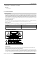
2. AC Power 2. AC POWER Overview • AC Power Cord Connection • AC Power Voltage • Switching ON/OFF 2.1 AC Power Cord Connection How to connect the AC Power Cord? Use the supplied power cord to connect your projector to the wall outlet. 1. Plug the female power connector into the male connector at the front side of the electronic block. (image 2-1) Image 2-1 Power connection 2.2 AC Power Voltage What is the AC Power Voltage? The power input voltage is autoranging between 100V (-10%) and 240V (+6%).
2. AC Power The projector can start now in the ’operational mode’ (image displayed) or in the ’stand by mode’, depending on the software setup. Stand by indication lamp : • no light up : projector in operational mode • red : projector is in stand by.
3. Source Connections 3. SOURCE CONNECTIONS Overview • Input Locations • Connecting a Composite Video source. • Connecting a S-Video source. • Connecting a RGB Analog source with composite sync • Connecting a RGB Analog source with Tri level composite sync • Connecting a Component source with composite sync • Connecting a Component source with Tri level composite sync • RS232 Connection • Communication Port for Communication With Peripherals • 12V Trigger output 3.
3. Source Connections 3.2 Connecting a Composite Video source. Which signal to the video input? Connect Composite video signals from a VCR, OFF air signal decoder, etc.. If a line multiplier is built in, the default position of this line multiplier soft option is ON (active). The video input signal will be displayed as a non interlaced image (= improved image stability).
3. Source Connections 3.3 Connecting a S-Video source. Chrominance The color component of a video signal that includes information about tint and saturation. Luminance The component of a video signal that includes information about its brightness. Which signal to the S-video input? Separate Y-luma/C-chroma signals for higher quality playback of Super VHS signals. If a line multiplier is built in, the default position of this line multiplier soft option is ON (active).
3. Source Connections Image 3-5 Input priority setting Depending on the priority setting in the ’Picture Tuning menu’, Video or S-Video can be displayed. If the setting is not correct, handle as follow : 1. Press ADJUST key to start up the adjustment mode. The main menu will be displayed. (menu 3-1) 2. Select Service Menus. 3. Press ENTER to select. A warning menu, risk of incorrect adjustment, will be displayed. (menu 3-2) 4. Press ENTER to continue if you are qualified, or EXIT if not.
3. Source Connections MAIN MENU Image control Iris control Sound control Function keys Service menus Select with ↑ or ↓ then to return Menu 3-1 Warning Risk of incorrect adjustment of the projector The following SERVICE menus are reserved to, and to be performed only by qualified personnel ! If qualified, press to continue, or if not, to return.
3. Source Connections Image 3-7 3.5 Connecting a RGB Analog source with Tri level composite sync Which signal can be connected to the input? RGB analog input terminals with tri level sync input or with tri level sync on green (BNC terminals). The projector detects automatically where the sync signal is located. Image 3-8 RGB3S or RG3sB connection RGB3S or RG3sB selection via the RCU 1. Press digit button 4. RGB3S or RG3sB selection via the local keypad 1.
3. Source Connections Image 3-9 3.6 Connecting a Component source with composite sync Which signal can be connected to the input? (R-Y)Y(B-Y) analog input terminals with sync input or with sync on green (BNC terminals). The projector detects automatically where the sync signal is located. Always use an interface (e.g. Barco Magik Interface R9828120) when a computer and local monitor have to be connected to the projector as the signal cable coming from the computer is limited to 60 cm due to interferences.
3. Source Connections Image 3-11 3.7 Connecting a Component source with Tri level composite sync Which signal can be connected to the input? (R-Y)Y(B-Y) analog input terminals with tri level sync input or with tri level sync on green (BNC terminals). The projector detects automatically where the sync signal is located. Image 3-12 Component input selection via the RCU 1. Press digit button 6. Component input selection via the local keypad 1. Press ADJUST key to start up the adjustment mode.
3. Source Connections Image 3-13 3.8 RS232 Connection RS232 A standard, single-ended (unbalanced) interconnection scheme for serial data communications. RS232 Input and RS232 Output of the projector The projector is equipped with a RS232 port that allows them to communicate with a computer. • Easy adjustment of the projector via a computer. • Allow storage of multiple projector configurations and set ups. • Wide range of control possibilities. • Address range from 0 to 255.
3. Source Connections 3.9 Communication Port for Communication With Peripherals Connecting a RCVDS 05 switcher to the projector • Up to 10 inputs (20 inputs when video and S-video) with the RCVDS 05 switcher (R9827880) and up to 90 inputs when 10 RCVDS switchers are linked via the 5-cable output modules. • Serial communication with the projector. • Remote control buttons on the RCVDS to control the projector (source selection and analog settings).
4. Getting Started 4. GETTING STARTED Overview • Batteries • RCU & Local keypad • Terminology overview • Switching on the projector • Using the RCU • Projector Address • Controlling the projector 4.1 Batteries Overview 4.1.1 • Battery installation • Battery replacement Battery installation How to install the battery Two batteries are packed together with the RCU. Before using your RCU, install first these batteries. 1.
4. Getting Started Image 4-1 Note, only important if more than one projector is installed in the room. The common address can be zero (0) or one (1). The standard RCU are setup for common address zero. To change the common address of the RCU, contact a BARCO service center. If it is necessary to program the projector address into the RCU, see chapter ’Getting Started’. Projector address has to be reprogrammed every time the battery is changed, the RCU will always switch to the default address. 4.
4. Getting Started Remote control functions. This remote control includes a battery powered infrared (IR) transmitter that allows the user to control the projector remotely. This remote control is used for source selection, control, adaptation and set up. It includes automatic storing of picture controls (Brightness, Sharpness...) and settings. Other functions of the remote control are : • switching between stand by and operational mode.
4. Getting Started 6 STBY standby button, to start projector when the power switch is switched on and to switch off the projector without switching off the power switch. Attention : Switching to Standby. When the projector is running and you want to go to standby, press the standby key for 2 seconds until the message ’Saving data, please wait’ is displayed. Do not press any longer on the standby key otherwise the projector will restart. 7 MUTE to interrupt the sound reproduction.
4. Getting Started 4.4 Switching on the projector How to switch on the projector? 1. Press the mains ON/OFF switch to switch on the projector.
4. Getting Started Do not display a stationary image with full brightness and contrast for longer than 20 min., otherwise you risk damage to the CRT’s. How to switch off the projector? 1. Use the same power switch to switch off the projector. 4.5 Using the RCU Pointing to the reflective screen 1. Point the front of the RCU to the screen surface. (image 4-4) Image 4-4 Hardwired Remote Input 1. Plug one end of the remote cable in the connector on the bottom of the RCU. (image 4-5) 2.
4. Getting Started Image 4-6 4.6 Projector Address 4.6.1 Controlling the projector Projector address Address installed in the projector to be individually controlled. Common address Default address. Projector will always execute the command coming from a RCU programmed with that common address. Why a projector address ? As more than one projector can be installed in a room, the separate projector should be separately addressable with an RCU or computer. There for each projector has its own address.
4. Getting Started 4.6.2 Displaying and Programming addresses Displaying the Projector Address on the Screen. 1. Press Address key (recessed key on the RCU) with a pencil. The projector’s address will be displayed in a ’Text box’ To continue using the RCU with that specific address, it is necessary to enter the same address with the digit buttons (address between 0 and 9) within 5 seconds after pushing the address key.
4. Getting Started Overview Picture controls When an image control is pressed, a text box with a bar scale, icon and function name of the control, e.g. ’brightness...’ appears on the screen (only if text is ON). See example screen. The length of the bar scale and the value of the numeric indication indicate the current memorized setting for this source. The bar scale changes as the control stick on the RCU is pressed or the + or - buttons on the local keypad.
4. Getting Started To restart the image : • Press Pause key. • Press EXIT key • Select a source number. The Freeze key (Only with Line Multiplier) When the Freeze key is pressed, the image is frozen until this key is pressed again (only with built in Line Multiplier).
5. Start up of the adjustment mode 5. START UP OF THE ADJUSTMENT MODE 5.1 How to start up the adjustment mode Start up using the RCU 1. Press the ADJUST key. The projector displays the main menu. (menu 5-1) MAIN MENU Image control Iris control Sound control Function keys Service menus Select with ↑ or ↓ then to return Menu 5-1 Start up using the local keypad 1. Press the ADJUST key. The projector displays the General Access menu. (image 5-1) 2.
5. Start up of the adjustment mode 5.2 How to adjust an analog control How to handle 1. Push the cursor keys up or down to select the analog control to be adjusted. 2. Press ENTER to confirm. When the analog control is adjusted the projector returns automatically to the General access menu. When you want to return to the Adjustment mode, press EXIT, otherwise select quit ADJUST and press ENTER to return to operational mode.
6. Main Menu 6. MAIN MENU Overview • Main Menu Overview • Image Control • IRIS Control • Sound Control • Function Keys • Service Menus 6.
6. Main Menu 6.2.1 Starting up the image controls To start up 1. Push the cursor key ↑ or ↓ to select Image Control. (menu 6-1) The selected item will change in color and a marker will be displayed in front of it. 2. Press ENTER to select. The Image Control menu will be displayed.
6. Main Menu Line Multiplier ON/OFF 1. Push the cursor key ↑ or ↓ to select Line Multiplier. (menu 6-5) 2. Press ENTER to toggle between ON and OFF. When in the ON state, all multiplier functions are selectable. IMAGE PROCESSING Line Multiplier : ON Multiplier Mode Motion Processing : ON Video Equalizing Noise Reduction Contrast Enhancement Select with ↑ or ↓ then to return Menu 6-5 6.2.2.
6. Main Menu Changing the scan rate 1. Push the cursor key ↑ or ↓ to select a new scan rate. (menu 6-9) 2. Press ENTER to activate this scan rate. 50Hz Vertical frequency of the image 1250 Lines Quantity of horizontal lines P = Non Interlaced = Progressive Scan Interlace mode I = Interlaced MULTIPLIER MODE 50Hz 50Hz 100Hz 50Hz 100Hz 625 lines 935 lines 625 lines 1250 lines 1250 lines P P P P I Select with ↑ or ↓ then to return Menu 6-9 6.2.2.
6. Main Menu How to adjust Video Equalizing? 1. Push the cursor key ↑ or ↓ to select Video Equalizing and press ENTER to select. (menu 6-11) The Video Equalizing menu will be displayed. (image 6-1) 2. Push the ← or → keys to select the desired frequency band (Low, Mid or High) or the Factory Preset : x. 3. Push the cursor key ↑ or ↓ to adjust the sharpness in the chosen frequency band (Low, Mid or High) or to scroll through the factory presets (x = 1 to 7).
6. Main Menu Image 6-2 Dynamic Noise Reduction bar scale 6.2.2.6 Contrast Enhancement What can be done? Enhancing the contrast results in a more dynamic image. How to adjust the Contrast Enhancement? 1. Push the cursor key ↑ or ↓ to select Contrast Enhancement and press ENTER to select. (menu 6-13) The Contrast Enhancement bar scale will be displayed. (image 6-3) 2. Push the cursor key ↑ or ↓ to adjust the Contrast Enhancement. 3. Press EXIT to return to the Image Processing menu.
6. Main Menu How to change the color temperature 1. Push the cursor key ↑ or ↓ to select Color Adjust. (menu 6-14) 2. Press ENTER to display the Color Adjust menu. (menu 6-15) 3. Push the cursor key ↑ or ↓ to select the desired color temperature. 4. Press ENTER to activate that color temperature. IMAGE CONTROL Image Processing Color Adjust Format Select COLOR ADJUST Broadcast Film Video Computer Custom 6.2.
6. Main Menu How to add a name? 1. Push the cursor key ↑ or ↓ to select the Format to which a name has to be added. (menu 6-18) 2. Press TEXT to display the compose menu. (menu 6-19) 3. The position of the character which will be edited, will be indicated with a digit. Push the cursor keys ↑, ↓, ← or → to select the first character. 4. Press ENTER to select the chosen character. This character will be inserted on the indicated position. The edit character indication will be incremented with one. 5.
6. Main Menu 6.3.1 Starting up the IRIS Controls Before starting one of the IRIS functions, be sure the projector has warmed up for at least 20 min. Only after 20 min the projector has reached its full specifications. How to start up 1. Push the cursor key ↑ or ↓ to select IRIS control. (menu 6-22) 2. Press ENTER to select. The IRIS control menu will be displayed.
6. Main Menu Starting the IRIS Auto Converge 1. Push the cursor key ↑ or ↓ to select IRIS Auto Converge. (menu 6-25) 2. Press ENTER to activate the autoconvergence function. The process starts and when successfully completed, the projector will return to image display of the current source. IRIS CONTROL IRIS Touch Up IRIS Auto Converge IRIS Full Alignment Select with ↑ or ↓ then to return Menu 6-25 6.3.
6. Main Menu Selecting the sound control. 1. Push the cursor key ↑ or ↓ to select Sound Control. (menu 6-27) 2. Press ENTER to select the Sound Control function. The Sound Control menu will be displayed. (menu 6-28) MAIN MENU SOUND CONTROL Image control Iris control Sound control Function keys Select sound mode : Service menus Normal Stereo Spacial Stereo Pseudo Stereo Mono Select with ↑ or ↓ then to return Select with ↑ or ↓ then to return Menu 6-27 Menu 6-28 6.
6. Main Menu How to enter the Service Menus 1. Push the cursor key ↑ or ↓ to select Service Menus. (menu 6-31) A warning will be displayed. (menu 6-32) "Risk of incorrect adjustment of the projector. The following SERVICE menus are reserved to and to be performed only by qualified personnel ! If qualified, press ENTER to continue, or if not, EXIT to return. 2. If qualified, press ENTER. (menu 6-33) If not qualified, press EXIT.
7. Entering the service menus 7. ENTERING THE SERVICE MENUS Overview • The Adjustment menus • Password Protection 7.1 The Adjustment menus What is available in the Adjustment menus A complete set of adjustments divided in different modes are available to adjust the projector, these different modes are: IRIS To autoalign and autoconverge the projector. Guided Guided should be selected if the user intends to perform a complete alignment of the projected image.
7. Entering the service menus Image 7-1 7.2 Password Protection Password Protection Some items in the Service menus are password protected. While selecting such an item, the projector asks to enter your password. Password Protection is only available when the password strap on the controller module is on. Contact a Barco authorized technician when no password is requested during the adjustment procedure and Password Protection is desired.
7. Entering the service menus Entering the Password via the local keypad When the compose password menus is displayed: 1. Select with the cursor the first digit of your password. (menu 7-5) 2. Press ENTER to select. 3. Select the next digit of your password. 4. Press ENTER to select. 5. Handle in the same way for the third and fourth digit.
7.
8. Random Access Adjustment Mode 8. RANDOM ACCESS ADJUSTMENT MODE Overview • Introduction • Random Access Overview • Selecting Setup Pattern • Random Access mode selection menu • Picture Tuning • Geometry Adjustments • Convergence Adjustment 8.1 Introduction How to start up Random Access Adjustment Mode? 1. Press the ADJUST key to start up the Adjustment Mode. The main Adjustment Mode menu will be displayed. 2. Push the cursor key ↑ or ↓ to highlight Random Access and press ENTER to select.
8. Random Access Adjustment Mode 8.
8. Random Access Adjustment Mode 8.3 Selecting Setup Pattern How to select the Setup Pattern? If an external source is connected to the projector, the following screen will be displayed. To select the desired setup pattern, handle as follow: 1. An external source is connected to the projector. Push the ↑ or ↓ keys to highlight the desired setup pattern and press ENTER to select.
8. Random Access Adjustment Mode 72.1/67 Super VGA 4 63.9/76 APOLLO How to select the desired Cross Hatch Frequency? To select a desired cross hatch frequency, handle as follow: 1. Push the cursor key ↑ or ↓ to highlight the desired Cross Hatch Frequency. (menu 8-3) 2. Push the ← or → keys to scroll to another page. 3. Press ENTER if the desired block is selected. INTERNAL # PATTERN kHz/Hz 15.6/50 15.6/60 31.2/50 31.5/60 31.2/50 31.
8. Random Access Adjustment Mode 8.5.1 Starting up Picture Tuning How to start up Picture Tuning? 1. Push the cursor key ↑ or ↓ to highlight Picture Tuning and press ENTER to select. (menu 8-5) The Picture Tuning menu will be displayed.
8. Random Access Adjustment Mode 8.5.2.2 Set a Fixed Color Balance How to select 1. Highlight one of the 4 preprogrammed color temperatures with the cursor keys. (menu 8-9) 2. Press ENTER to display the image with the desired color balance. COLOR BALANCE FIXED COLOR BALANCE 3200 5400 6500 9300 CUSTOM WHITE RED & BLUE CUSTOM BLACK RED & BLUE BALANCE GREEN BALANCE GREEN Select with arrow keys then adjust red with ↑ or ↓ Blue with ← or → to return Menu 8-9 8.5.2.
8. Random Access Adjustment Mode 8.5.2.4 Custom Color Balance, Black Balance adjustment How to adjust 1. Push the cursor keys ↑, ↓, ← or → to select Red & Blue below Custom black Balance. (menu 8-11) 2. Press ENTER to activate the adjustment. 3. Push the cursor key ↑ or ↓ to adjust the red cut-off. 4. Push the cursor key ← or → to adjust the blue cut-off. A bar scale indicates the amount of adjustment. 5. Press ENTER to return to the Color Balance menu. 6.
8. Random Access Adjustment Mode The possibility is offered to decode the NTSC video signals via the normal American IRE standard or via the European EBU standard. How to set up ? How to set up ? 1. Push the cursor key ↑ or ↓ to select Decoding. (menu 8-13) 2. Press ENTER to toggle between IRE and EBU.
8. Random Access Adjustment Mode How to adjust Peaking? 1. Push the cursor key ↑ or ↓ to highlight Peaking and press ENTER. (menu 8-15) Note: During the creation of new settings for a RGB source the corresponding peaking is switched on as default. The Peaking menu will be displayed. (menu 8-16) The following frequency areas are available: Low Frequency Peaking 15–45Hz Mid Frequency Peaking 45–85Hz High Frequency Peaking 85–110Hz 2.
8. Random Access Adjustment Mode How to start up the Line Multiplier settings? 1. Push the cursor key ↑ or ↓ to highlight Line Multiplier and press ENTER to select. (menu 8-17) The Image Processing menu will be displayed.
8. Random Access Adjustment Mode 8.5.7.4 Output Mode What can be done? Within the output mode menu, it is possible to select a new output mode for a given input signal. The input signal can be: • interlaced. • non-interlaced. How to adjust the Output Mode? 1. Push the cursor key ↑ or ↓ to highlight Output Mode and press ENTER to select.
8. Random Access Adjustment Mode Image 8-1 Video Equalizing menu 8.5.7.6 Noise Reduction What can be done? Noisy, lower quality video images can be ameliorated by use of the Noise Reduction feature. How to adjust Noise Reduction? 1. Push the cursor key ↑ or ↓ to highlight Noise Reduction and press ENTER to select. (menu 8-26) The Dynamic Noise Reduction bar scale will be displayed. (image 8-2) 2. Push the cursor key ↑ or ↓ to adjust the Noise Reduction. 3.
8. Random Access Adjustment Mode How to adjust the Contrast Enhancement? 1. Push the cursor key ↑ or ↓ to highlight Contrast Enhancement and press ENTER to select. (menu 8-27) The Contrast Enhancement bar scale will be displayed. (image 8-3) 2. Push the cursor key ↑ or ↓ to adjust the Contrast Enhancement. 3. Press EXIT to return to the Image Processing menu.
8. Random Access Adjustment Mode 8.5.7.9.1 Starting Up Advanced Settings How to start up Advanced Settings? 1. Push the cursor key ↑ or ↓ to highlight Advanced Settings and press ENTER to select. (menu 8-29) The Advanced settings menu will be displayed.
8. Random Access Adjustment Mode How to adjust Luminance Delay? 1. Push the cursor key ↑ or ↓ to highlight Luminance Delay and press ENTER to select. (menu 8-32) The Luminance Delay bar scale will be displayed. (image 8-4) 2. Push the cursor key ↑ or ↓ to adjust the Luminance Delay until the color shift is eliminated. 3. Press EXIT to return to the Line Multiplier menu.
8. Random Access Adjustment Mode How to toggle Clamp Gating On/Off? 1. Push the cursor key ↑ or ↓ to highlight Clamp Gating. (menu 8-34) 2. Press ENTER to toggle Clamp Gating On/Off. Note: Default Clamp Gating is set to Off.
8. Random Access Adjustment Mode How to adjust Coring? 1. Push the cursor key ↑ or ↓ to highlight Coring and press ENTER to select. (menu 8-36) The Coring bar scale will be displayed. (image 8-5) 2. Push the cursor key ↑ or ↓ to adjust the Coring. 3. Press EXIT to return to the Limo Pro Options menu. LINE MULTIPLIER CORING LTI CTI WARNING: ADVANCED ADJUSTMENT SHOULD BE PERFORMED ONLY BY QUALIFIED PERSONNEL Select with ↑ or ↓ then to return Menu 8-36 Image 8-5 8.5.7.10.
8. Random Access Adjustment Mode How to adjust LTI? 1. Push the cursor key ↑ or ↓ to highlight LTI and press ENTER to select. (menu 8-37) The Coring bar scale will be displayed. (image 8-7) 2. Push the cursor key ↑ or ↓ to adjust the LTI value. Note: Only 7 steps are possible. 3. Press EXIT to return to the Limo Pro Options menu.
8. Random Access Adjustment Mode How to adjust CTI? 1. Push the cursor key ↑ or ↓ to highlight CTI and press ENTER to select. (menu 8-38) The LTI bar scale will be displayed. (image 8-9) 2. Push the cursor key ↑ or ↓ to adjust the CTI value. Note: Only 7 steps are possible. 3. Press EXIT to return to the Limo Pro Options menu.
8. Random Access Adjustment Mode 8.6 Geometry Adjustments Overview • Starting Up Geometry • Horizontal Phase Adjustment • Raster Shift Adjustment • Left-Right (East-West) Adjustment • Top-Bottom (Nord-South) Adjustment • Size Adjustment • Vertical Linearity Adjustment • Blanking Adjustments 8.6.1 Starting Up Geometry What can be done? The geometry adjustments have to be done only on the green image. These adjustments are automatically implemented for the other color images.
8. Random Access Adjustment Mode How to adjust the Horizontal Phase? 1. Push the cursor key ↑ or ↓ to highlight Horizontal Phase and press ENTER to select. (menu 8-42) The Horizontal Phase Text box will be projected in the middle of the external image. A bar scale and a number indicator (between 0 and 100) on the screen give a visual indication of the horizontal phase adjustment. (image 8-10) 2. If the raster shift is correctly adjusted, the H Phase text box is projected in the middle of the raster.
8. Random Access Adjustment Mode Image 8-11 How to adjust the Raster Shift? 1. Push the cursor key ↑ or ↓ to highlight Raster Shift and press ENTER to select. (menu 8-43) The Raster Shift menu will be displayed. 2. First push the ↑ or ↓ keys to highlight Coarse Green and press ENTER to select. (menu 8-44) 3. Use the cursor keys to perform a Coarse Raster Shift and press ENTER to continue. 4. Push the ↑ or ↓ keys to highlight Coarse Red Horz and press ENTER to select. 5.
8. Random Access Adjustment Mode Start up 1. Push the cursor key ↑ or ↓ to highlight LEFT-RIGHT. (menu 8-45) 2. Press ENTER to select. The Left-Right menu will be displayed.
8. Random Access Adjustment Mode Image 8-12 (A) (B) (C) (D) (E) (F) Vertical Centerline bow Vertical Centerline skew Right bow Right keystone Left bow Left keystone How to enter an alignment? 1. Push the cursor key ↑ or ↓ to highlight a function. 2. Press ENTER to activate this function. 3. Press EXIT to return.
8. Random Access Adjustment Mode How to adjust the Seagull correction 1. Push the cursor key ↑ or ↓ to highlight SEAGULL CORRECTION. (menu 8-47) 2. Press ENTER to activate. Eliminate the deformation by pushing the cursor key ← or → until a straight line is obtained (image 8-13) LEFT-RIGHT (E-W) V CENTERLINE BOW V CENTERLINE SKEW RIGHT BOW RIGHT KEYSTONE LEFT BOW LEFT KEYSTONE SEAGULL CORRECTION Select with ↑ or ↓ then to return Menu 8-47 Image 8-13 Seagull correction 8.6.
8. Random Access Adjustment Mode Possible adjustments The following adjustments can be executed • Horizontal centerline bow • Horizontal centerline skew • Top bow • Top keystone • Bottom bow • Bottom keystone All adjustment are indicated on the screen with the function name, a bar scale and a number between 0 and 100. Adjust the next alignments until the vertical lines are straight.
8. Random Access Adjustment Mode Image 8-14 Top-Bottom corrections (A) (B) (C) (D) (E) (F) Vertical centerline Bow Vertical centerline Skew Top Bow Top Keystone Bottom Bow Bottom Keystone How to enter an alignment? 1. Push the cursor key ↑ or ↓ to highlight a function. 2. Press ENTER to activate this function. 3. Press EXIT to return.
8. Random Access Adjustment Mode What can be done with the Seagull correction Use this correction after the image has been adjusted with top and bottom bow and keystone. If still a deformation (like a seagull) on top and bottom of the image is visible, proceed to the seagull correction. Due to interaction, it is possible that the top and bottom bow have to be readjusted after adjusting the seagull correction to obtain an improved image. The default value on the bar scale of this correction is 50.
8. Random Access Adjustment Mode Image 8-16 Size adjustment A B Vertical size adjustment Horizontal size adjustment In order to avoid loss of resolution in the projected image and to ensure maximum CRT longevity, do not use an excessively small size setting. If the internal # pattern was selected, this pattern remains on the screen, if the genlocked pattern was selected, the external source will be displayed. How to adjust the Size? 1.
8. Random Access Adjustment Mode Image 8-17 Image 8-18 Horizontal Size Adjustment Image 8-19 Vertical Size Adjustment 8.6.7 Vertical Linearity Adjustment What can be done? The vertical linearity adjustment function corrects for vertical non-linearities which extend from the center of the image to the top and bottom of the image. Start up 1. Push the cursor key ↑ or ↓ to highlight V Linearity. (menu 8-52) 2. Press ENTER to activate. 3.
8. Random Access Adjustment Mode Image 8-20 Vertical linearity 8.6.8 Blanking Adjustments What can be done? Blanking adjustments affect only the edges of the projected image and are used to frame the projected image on to the screen and to hide or black out unwanted information. The following blanking adjustments are available: • Top. • Bottom. • Left. • Right.
8. Random Access Adjustment Mode How to adjust the Blanking? 1. Push the cursor key ↑ or ↓ to highlight Blanking and press ENTER to select. (menu 8-53) The Blanking menu will be displayed. (menu 8-54) 2. Push the cursor key ↑ or ↓ to highlight the desired blanking position and press ENTER to select. (image 8-22) 3. Push the cursor keys to adjust the blanking and press ENTER to confirm. 4. Press EXIT to return to the Geometry menu.
8. Random Access Adjustment Mode Image 8-23 Convergence Adjustment Adjustment order Adjust first the green only when available and continue with red on green and blue on green. How to start up Convergence? 1. Push the cursor key ↑ or ↓ to highlight Convergence and press ENTER to select. (menu 8-55) The Convergence menu will be displayed.
8.
9. Service Mode 9. SERVICE MODE Overview • Introduction • Service Mode Overview • Projector Set up • Memory Management • Common Settings • I2C Diagnostics 9.1 Introduction How to start up Service Mode? 1. Push the cursor key ↑ or ↓ to highlight Service and press ENTER to select. (menu 9-1) The Service menu will be displayed.
9. Service Mode 9.
9. Service Mode 9.3.1 Starting Up Projector Set-Up Start up 1. Push the cursor key ↑ or ↓ to highlight Projector Set-Up and press ENTER to select. (menu 9-3) The Projector Set-Up menu will be displayed.
9. Service Mode How to start up Total Run Time? 1. Push the cursor key ↑ or ↓ to highlight Total Run Time and press ENTER to select. (menu 9-7) The Total Run Time screen will be displayed, the System Runtime indicates the amount of time the projector has played since its first start up at the factory.
9. Service Mode What can be done? 1. Push the cursor key ↑ or ↓ to highlight Change Language. (menu 9-11) 2. Press ENTER to display the language menu. (menu 9-12) 3. Push the cursor key ↑ or ↓ to highlight the desired language. 4. Press ENTER to change to that language.
9. Service Mode By default the Baudrate is set to 9600. How to Change the Baudrate? 1. Push the cursor key ↑ or ↓ to highlight Change Baudrate and press ENTER to select. (menu 9-15) The Baudrate menu will be displayed, the actual Baudrate will be highlighted. (menu 9-16) 2. Push the cursor key ↑ or ↓ to highlight the desired Baudrate and press ENTER to confirm. 3. Press EXIT to return to the Projector Set-Up menu.
9. Service Mode How to change the Common Address? 1. Push the ↑ or ↓ keys to highlight Common Address. 2. Press ENTER to toggle the Common Address between ’0’ and ’1’. (menu 9-18) 3. Press EXIT to return to the Service Mode menu. PROJECTOR SET-UP IDENTIFICATION TOTAL RUN TIME CHANGE PASSWORD CHANGE LANGUAGE CHANGE PROJECTOR ADDRESS CHANGE BAUDRATE POWER UP MODE: operating COMMON ADDRESS: 0 BARCO LOGO Select with ↑ or ↓ then to return Menu 9-18 9.3.
9. Service Mode How to add the Barco Logo 1. Push the cursor key ↑ or ↓ to highlight Barco Logo. (menu 9-19) 2. Press ENTER to select. The BARCO logo menu will be displayed on the screen. (menu 9-20) Within this menu, four toggle settings are available. Mode[ON/OFF] Select mode and toggle with ENTER between ON and OFF ON : BARCO logo will be displayed on the screen when leaving the adjustment mode.
9. Service Mode 9.4.1 Starting Up Memory Management How to start up the Memory Management? 1. Push the cursor key ↑ or ↓ to highlight Memory Management and press ENTER to select. (menu 9-21) The Memory Management menu will be displayed.
9. Service Mode How to Delete a Block? 1. Push the cursor key ↑ or ↓ to highlight Delete a Block and press ENTER to select. (menu 9-25) The Delete a Block menu will be displayed. (menu 9-26) 2. Push the cursor key ↑ or ↓ to to select a block. 3. Press ENTER to delete the selected block. A confirmation screen will be displayed. 4. Press ENTER to confirm, press EXIT to cancel the deletion.
9. Service Mode How to set All settings to Midposition? 1. Push the cursor key ↑ or ↓ to highlight All Settings to Midpos. (menu 9-28) 2. Press ENTER to select. A confirmation screen will be displayed. 3. Press ENTER to confirm, press EXIT to cancel the reset.
9. Service Mode How to Undo Convergence R & B to Midposition? As long as the projector is playing on the same source (= same adjustment block) it is possible to return to the previous settings. Undo R&B Convergence to Mid is displayed in stead off R&B Convergence to Mid. 1. Push the cursor key ↑ or ↓ to highlight Undo R&B Convergence to Mid. (menu 9-31) 2. Press ENTER to reset the All settings to the previous settings.
9. Service Mode 9.5 Common Settings Overview • 9.5.1 Starting Up Common Settings • G2 Adjustment • CRT Run In Cycle • Projector Warm Up • Memory Banks Starting Up Common Settings How to start up Common Settings? 1. Push the cursor key ↑ or ↓ to highlight Common Settings and press ENTER to select. (menu 9-34) The Common Settings menu will be displayed.
9. Service Mode If no such a block is available, the projector cannot run CRT Run In Cycle and leaves the adjustment mode. If you still want to run CRT run in cycle, create first a memory block on an internal # pattern and restart CRT Run In Cycle . What is done? A flashing white image (5sec. on, 5 sec. off) is generated for 5 min. on the first internal block. In the next 5 min., the next internal block available will be used to generate the flashing white image.
9. Service Mode How to select 1. Push the cursor key ↑ or ↓ to highlight Memory Banks. (menu 9-41) 2. Press ENTER to toggle between ON and OFF. ON different memory banks available OFF only one memory bank available. If different memory banks are available for a source and the memory bank option is toggled to OFF, only the first memory bank will be used to display the source.
9.
10. Programmable Function Keys 10. PROGRAMMABLE FUNCTION KEYS 10.1 Programming a Function Keys What can be done with these keys? The five function keys on top of the remote control can be programmed as short cut keys (quick access) to almost any adjustment function. See list further in this chapter. How can a Function key be programmed? A function key can only be programmed when in the service menus. 1. Scroll through the menus until the desired function is on the menu. 2.
10. Programmable Function Keys 10.2 Different function which can be programmed.
11. Messages, Warnings and Failures 11. MESSAGES, WARNINGS AND FAILURES Overview • Messages • Warnings • Failures 11.1 Messages Messages INPUT 01 RGB2 Fh=064kHz Fv=060Hz When selecting a new source, following information about this source will be displayed on the screen: Source number, horizontal and vertical frequencies of the displayed source. SOURCE 01 RGB2 Announcement of the selected source. enter password XXXX Message to enter your password, password contains 4 digits.
11. Messages, Warnings and Failures 11.3 Failures Failures 102 FAILURE I2C error addr.: 7FH3 Hardware failure. Call a qualified service technician for repair. FAILURE short circuit on I2C bus Hardware failure. Call a qualified service technician for repair. FAILURE RCVDS communication error Serial communication error between the RCVDS and the projector. FAILURE invalid input Input not valid FAILURE PC communication error Error in the communication between the projector and the PC.
A. Source Numbers 81 — 86 and 91 — 96 A. SOURCE NUMBERS 81 — 86 AND 91 — 96 A.1 Projector without any 800 peripheral connected Overview The source numbers 81 - 86 and 91 - 96 do not correspond to physical inputs. An additional adjustment file can be created for these source numbers. This file can contain different settings. The relationship between sources 1 - 6 and 91 - 96 or between 1 - 6 and 81 - 86 is shown in the diagram below.
A. Source Numbers 81 — 86 and 91 — 96 source input 3 source input 3 file C source input 93 file C’ ... source input 6 source input 6 file F source input 96 file F’ Follow the same procedure as for a projector without a 800 peripheral connected. A.2.2 Source numbers 81 — 86 Overview Only valid if no input module is connected to slot 81 - 86 of a RCVDS05. The source numbers 81 - 86 correspond to the physical inputs 1 - 6 of the projector. e.g.
Glossary GLOSSARY Chrominance The color component of a video signal that includes information about tint and saturation. Common address Default address. Projector will always execute the command coming from a RCU programmed with that common address. CTI Color transient improvement. To improve the transition from one color to another. Interlaced Short for interlaced scanning. Also called line interlace.
Glossary 106 R5976584 BARCO CINE7 26022003
Index INDEX A D AC Power 9 Power Cord 9 Connection 9 Power Voltage 9 Switching ON/OFF 9 Address 27–28 Program 28 RCU 28 Projector 27 Adjustment 45, 49 menus 45 Random Access 49 Introduction 49 Adjustment mode 31–32 Adjust 32 Start up 31 Via the local keypad 31 Via the RCU 31 Advanced Settings 61–62 Start up 62 Decoding F Factory Preset Frequencies Factory presets 67 Failures 101–102 FCC Statement 5 Fire Hazard 6 Format Select 39–40 Add name 39 Selecting 39 Storing settings 40 Function keys 99–100 Possi
Index L Language 86 Change 86 Limo Pro 64–66 Coring 64 CTI 66 LTI 65 Options 64 Start up 64 Limo Pro Options 64 Line multiplier 67 Advanced settings 67 Factory presets 67 Line Multiplier 34–35, 57–63 Advanced Settings 61–63 Clamp Gating 63 Luminance Delay 62 Start up 62 Time Base Correction 62 Vertical Sync Reference 63 Changing setting 34 Contrast Enhancement 60 Motion Processing 58 Multiplier mode 35 Noise Reduction 60 Output Mode 59 settings 57–58 Start up 57 Switching on/off 58 Split Screen 61 Video Eq
Index Size Adjustment 76 Sound Control 42 Source connections 12–13, 15–18 Component source 17–18 With composite sync 17 With Tri level composite sync 18 Composite video 12 RGB analog 15–16 With composite sync 15 With Tri level composite sync 16 S-Video 13 Source Connections 11 Source numbers 103–104 with 800 peripheral 103–104 source numbers 81 — 86 104 source numbers 91 — 96 103 without 800 peripheral 103 Split Screen 61 On/Off 61 Stand By Mode 25 Start up 25 Stationary Image Warning 26 Switch off 26 R597
Index 110 R5976584 BARCO CINE7 26022003
Revision Sheet To: Barco nv Home Cinema/Documentation Noordlaan 5, B-8520 Kuurne Phone: +32 56.36.84.30, Fax: +32 56.36.88.62 E-mail: antoon.dejaegher@barco.com, Web: www.homecinema.barco.