HOME CINEMA BARCO CINE7 R9010040 R9010050 INSTALLATION MANUAL 26022003 R5976585/00
Barco nv Home Cinema Noordlaan 5, B-8520 Kuurne Phone: +32 56.36.84.30 Fax: +32 56.36.88.62 E-mail: salesassistantht.bci@barco.com Visit us at the web: www.homecinema.barco.
Copyright © All rights reserved. No part of this document may be copied, reproduced or translated. It shall not otherwise be recorded, transmitted or stored in a retrieval system without the prior written consent of BARCO. Federal Communication Commission (FCC Statement) This equipment has been tested and found to comply with the limits for a class A digital device, pursuant to Part 15 of the FCC rules.
Table of contents TABLE OF CONTENTS 1. Safety Instructions .. .. .. .. .. .. .. .. .. .. .. .. .. .. .. .. .. .. .. .. .. .. .. .. .. .. .. .. .. .. .. .. .. .. .. .. .. .. .. .. .. .. .. .. .. .. .. .. . 3 1.1 Safety Instructions . . . . . . . . . . . . . . . . . . . . . . . . . . . . . . . . . . . . . . . . . . . . . . . . . . . . . . . . . . . . . . . . . . . . . . . . . . . . . . . . . . . . . . . . . . . . . . . . . . . . . . . . . . . . . . . . . . . . . 3 2. Packaging and Dimensions . .. .. .. .. .
Table of contents 2 R5976585 BARCO CINE7 26022003
1. Safety Instructions 1. SAFETY INSTRUCTIONS Overview • Safety Instructions 1.1 Safety Instructions Notice on Safety This equipment is built in accordance with the requirements of the international safety standards EN60950, UL 1950 and CSA C22.2 No.950, which are the safety standards of information technology equipment including electrical business equipment.
1. Safety Instructions in a residential area is likely to cause harmful interference in which case the user will be required to correct the interference at his own expense. The use of shielded cables is required to comply within the limits of Part 15 of FCC rules and EN55022. • All the safety and operating instructions should be read before using this unit. • The safety and operating instructions manual should be retained for future reference.
1. Safety Instructions On Installation • Do not place this equipment on an unstable cart, stand, or table. The product may fall, causing serious damage to it. • Do not use this equipment near water. • Slots and openings in the cabinet and the back or bottom are provided for ventilation; to ensure reliable operation of the product and to protect it from overheating, these openings must not be blocked or covered.
1.
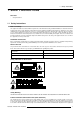
2. Packaging and Dimensions 2. PACKAGING AND DIMENSIONS 2.1 Projector Packaging Way of Packaging The projector is packed in a carton box. To provide protection during transportation, the projector is surrounded with foam. The package is secured with banding and fastening clips. To unpack 1. Release the fastening clips. 2. Remove the banding. Handle as shown in the drawing. (image 2-1) 3. Take the projector out of its shipping carton and place it on a table.
2.
3. Installation Guidelines 3. INSTALLATION GUIDELINES Overview • General Installation Guidelines • Configuration • Lens Formulas • Scan Adaptation 3.1 General Installation Guidelines Ambient temperature check Careful consideration of things such as image size, ambient light level, projector placement and type of screen to use are critical to the optimum use of the projection system. Max. ambient temperature : 40 C or 104 F Min.
3. Installation Guidelines Screens are rated by how much light they reflect (or transmit in the case of rear projection systems) given a determined amount of light projected toward them. The ‘GAIN’ of a screen is the term used. Front and rear screens are both rated in terms of gain. The gain of screens range from a white matte screen with a gain of 1 (x1) to a brushed aluminized screen with a gain of 10 (x10) or more.
3. Installation Guidelines Image 3-2 Possible configurations Positioning the projector The projector should be installed perpendicular with the screen on a distance PD and water leveled in both directions.
3. Installation Guidelines Image 3-3 Projector positioning B A Distance between ceiling and top of the screen Correction value, extra value to be added to B to obtain the correct installation position. (In some cases the A value can be negative). CD Total distance between projector and distance. SW Screen width PD Perpendicular distance between screen and projector. CD = A + B.
3. Installation Guidelines 3.4.1 Access to the scan controls How to get access 1. Turn both lock screws with a screwdriver or a coin counter clockwise. 2. Lift up and pivot the top cover. (image 3-4) 3. Support the top cover with the hand, no support is incorporated. During some installations it will become handy to remove the top cover totally. Therefore, continue with step 6. 4. To open the chassis, loosen both indicated retaining screws. (image 3-5) 5.
3. Installation Guidelines Image 3-6 Chassis open Image 3-7 Removing the top cover 3.4.2 Scan Inversion Horizontal scan inversion Three connectors are used, one for each horizontal deflection coil. When changing the horizontal scan, insure that all three connectors are set in the same position. See position of the connectors for the corresponding projector configuration.
3. Installation Guidelines Image 3-8 Scan connectors Vertical Scan Inversion Three connectors are used, one for each vertical deflection coil. When changing the vertical scan, insure that all three connectors are set in the same position. See position of the connectors for the corresponding projector configuration. Top view of the connectors; upper three connectors for horizontal scan inversion, lower three for vertical scan inversion (image 3-8). Convergence Connectors Three connectors are used.
3. Installation Guidelines Check procedure This check procedure can only be done after power (mains) connection. So, first continue with the projector set up and the connections and then return to this checking procedure. 1. Switch on the projector 2. Press ADJUST to start up the adjustment mode. (menu 3-1) 3. Push the cursor key ↑ or ↓ to select Service and press ENTER. The service menu will be displayed. (menu 3-2) 4. Push the cursor key ↑ or ↓ to select PROJECTOR SET UP and press ENTER.
4. Projector Set up 4. PROJECTOR SET UP Overview • Password strap 4.1 Password strap What is allowed? With a strap on the controller unit, the important projector adjustments can be protected with a password. When the password feature is enabled (strap mounted on both legs), the customer has to enter a password before he can enter the specific adjustment. Gaining access 1. Open the top cover, see Installation Guidelines, page 9 . 2. Open the chassis. 3. Mount or remove the strap.
4.
5. Installation Adjustment 5. INSTALLATION ADJUSTMENT Overview • Entering the Service menus • Starting up the Installation Adjustment Mode • Password Protection • Overview Installation mode • Scheimpflug Adjustment • Optical Lens Focusing • Electrical focusing • Raster Centering • CRT Projection Angle Adjustment 5.1 Entering the Service menus How to enter the Adjustment menus with the RCU? 1. Press the ADJUST key. The Main menu will be displayed. (menu 5-1) 2.
5. Installation Adjustment Image 5-1 5.2 Starting up the Installation Adjustment Mode How to Start Up the Installation Adjustment Mode? 1. Push the cursor key ↑ or ↓ to select Installation and press ENTER to select. (menu 5-5) A warning will be displayed on the screen. (menu 5-6) 2. In case you are a qualified and authorized service person. Press ENTER to start up the first step of the installation mode: Projector Position.
5. Installation Adjustment Entering the Password with the RCU The Password contains 4 digits, when the projector asks to enter your password: 1. Enter the digits with the numeric keys on the RCU (e.g.: 2319). For each digit entered, a ’X’ appears on the screen under the displayed text ’enter password’ (menu 5-7) enter password XXXX Menu 5-7 Entering the password with the local keypad. 1. Select with the cursor keys to select the first digit of your password and press ENTER. (menu 5-8) 2.
5. Installation Adjustment Necessary tools nutdriver 11 mm or screwdriver Set up the scheimpflug range 1. Open the top cover, see Installation Guidelines, page 9 . 2. Loosen the lens bolts (do not remove them), and slide the lens to the front until the scheimflug ring can move freely. (image 5-2) 3. Push the scheimpfug ring to its correct position (front view). - range 1 : to the right - range 2 : in the middle - range 3 : to the left (image 5-3) 4.
5. Installation Adjustment 5.6 Optical Lens Focusing What can be done? The optical focusing procedure is performed separately for each lens. The appropriate CRT will be switched on as the user proceeds through the optical focusing adjustment sequence. How to focus 1. To focus the center, loosen the wing nut at the rear end of the lens. 2. Rotate the lens barrel until the center fo the image is clearly focussed. 3. Loosen the wing nut at the front end of the lens. 4.
5. Installation Adjustment Image 5-4 Electrical focus adjustment The blue focus has been factory adjusted for optimal color reproduction. Readjustment of the blue focus will effect color temperature and color tracking. 5.8 Raster Centering Introduction The raster must be centered on the CRT faceplate of each tube, therefore, it is necessary to look into the lenses.
5. Installation Adjustment Image 5-5 CRT Phosphor Width How to center the raster? 1. Press the ENTER key to activate the raster on the Green CRT faceplate. 2. Look into the Green lens and shift the raster with the cursor keys until it is centered in the middle of the CRT faceplate. (image 5-6) 3. Press the ENTER key to activate the raster on the Red CRT faceplate. 4. Shift the Red raster with the cursor keys until the raster is centered on the CRT faceplate. 5.
5. Installation Adjustment CRT PROJECTION ANGLE ADJUSTMENT CRT PROJECTION ANGLE IS THE FIRST STEP OF STATIC CONVERGENCE ADJUSTMENT IT IS CRITICAL THAT THE RASTERS ARE CENTERED ON THE CRT FACE PLATES PRIOR TO PERFORMING THIS STEP to continue to return Menu 5-11 Never try to correct this misalignment with the shift correction or the static convergence controls. These shift correction controls may only be applied to correct small errors which cannot be corrected by the CRT angle adjustment.
5.
5.
6. G2 Adjustment 6. G2 ADJUSTMENT 6.1 Start up the G2 adjustment Start up 1. Enter the adjustment mode by pressing ADJUST. (menu 6-1) 2. Highlight Service. 3. Press ENTER to start up the service mode. 4. Highlight Common settings. (menu 6-2) 5. Press ENTER. 6. Highlight G2 adjust. (menu 6-3) 7. Press ENTER. A safety notice will be displayed to warn the operator. (menu 6-4) If you are qualified, press ENTER to continue with the G2 adjustment, otherwise press EXIT to return to the service menu.
6. G2 Adjustment Image 6-1 The best result is obtained in a completly dark room or by looking into the lenses, but be aware that brightness and contrast are on a high level.
Revision Sheet To: Barco nv Home Cinema/Documentation Noordlaan 5, B-8520 Kuurne Phone: +32 56.36.84.30, Fax: +32 56.36.88.62 E-mail: antoon.dejaegher@barco.com, Web: www.homecinema.barco.