
Installation manual


3. Installation Guidelines
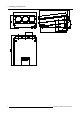
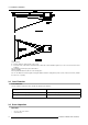
Image 3-8
Scan connectors
Vertical Scan Inversion
Three connectors are used, one for each vertical deflection coil. W hen ch anging the v ertical s can, insure that all three connectors
are set in the same position. See position of the connectors for the co rresponding projector configuration.
Top view of the connectors; upper three connectors for horizontal scan inv ersion, lower three for vertical scan inversion (image 3-8).
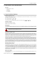
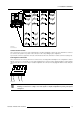
Convergence Connectors
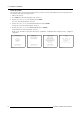
Three c onnectors are used. T he position of these connectors has to be changed when switching from one co nfiguration to another.
With an open chas sis, for a front-table or a rear ceiling configuration, the conne ctors m ust be plugged in with the contacts upw ards
(away from the tubes). For a front-ceiling or rear-table con figuration, the connectors must be plugged in with the contacts facing the
tubes
Image 3-9
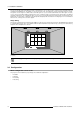
After scan inversion, close the ch assis a nd close the top cover. Reconnect the pow er cord to the wall o utlet.
Switching over from floor to ceiling or vice versa requires a comp lete readjustme nt of p icture geom etry an d
convergence.
R5976585 BARCO CINE7 26022003 15