Coronis 3MP LED Display User Guide MDCG-3221 K5902060/03 12/01/2015
Barco nv President Kennedypark 35, 8500 Kortrijk, Belgium Phone: +32 56.23.32.11 Fax: +32 56.26.22.62 Support: www.barco.com/esupport Visit us at the web: www.barco.
Table of contents TABLE OF CONTENTS 1. Welcome! .......................................................................................... 3 1.1 1.2 1.3 About the product .. .. .. .. .. .. .. .. .. .. .. .. .. .. .. .. .. .. .. .. .. .. .. .. .. .. .. .. .. .. .. .. .. .. .. .. .. .. .. .. .. .. .. .. .. .. . 3 Symbols . .. .. .. .. .. .. .. .. .. .. .. .. .. .. .. .. .. .. .. .. .. .. .. .. .. .. .. .. .. .. .. .. .. .. .. .. .. .. .. .. .. .. .. .. .. .. .. .. .. .. .. . 3 What’s in the box. .. .. .. ..
Table of contents 6. Repackaging instructions ...................................................................... 33 6.1 6.2 Replacing the protection buffer . .. .. .. .. .. .. .. .. .. .. .. .. .. .. .. .. .. .. .. .. .. .. .. .. .. .. .. .. .. .. .. .. .. .. .. .. .. .. . 34 Repacking your display.. .. .. .. .. .. .. .. .. .. .. .. .. .. .. .. .. .. .. .. .. .. .. .. .. .. .. .. .. .. .. .. .. .. .. .. .. .. .. .. .. .. .. . 35 7. Cleaning your display ................................................
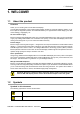
1. Welcome! 1. WELCOME! 1.1 About the product Overview Thank you for choosing this Coronis 3MP LED Display! Coronis 3MP LED Display is the industry-leading display system for grayscale radiology imaging. It delivers optimum diagnostic precision and workflow efficiency for high-resolution PACS imaging, CT, MRI, chest radiology, angiography, etc. 50 more shades of gray Barco’s high-bright LED backlights render more Just Noticeable Differences to help you see more shades of gray.
1. Welcome! Info, term definition. General info about the term Note: gives extra information about the described subject Tip: gives extra advice about the described subject 1.
2. Parts, controls and connectors 2. PARTS, CONTROLS AND CONNECTORS 2.
2. Parts, controls and connectors 2.
2. Parts, controls and connectors Connector compartment cover open Image 2-3 Rear view with open connector compartment cover 1 +24 VDC power input 5 2 +5 VDC, 0.5A power output 6 Ethernet connector (see note below) USB upstream connector 3 DisplayPort video input 7 USB downstream connector 4 DVI video input The Ethernet connection is used for maintenance purposes and is not supported for user application.
2.
3. Display installation 3. DISPLAY INSTALLATION Prior to installing your Coronis 3MP LED Display and connecting all necessary cables, make sure to have a suitable display controller physically installed in your computer. If you are using a Barco display controller, please consult the user guide delivered with it to do this. For a list of compatible display controllers, please refer to the latest version of the compatibility matrix available on my.barco.
3. Display installation 3. To change from portrait to landscape, turn the panel counterclockwise. 4. To change from landscape to portrait, turn clockwise. If, after installing the display of the system, you change the panel orientation while an image is on the screen, the result depends on the graphic board and the resolution of the image. In some cases the image will be rotated automatically, in other cases it will not be rotated (e.g., when pixels would be lost after rotation).
3. Display installation 3.4 Connecting the signal cables CAUTION: Only connect one of the two video links. Connecting both inputs simultaneously will result in driver errors. To connect the signal cables to the display: To get access to the connectors, remove the connector compartment cover. See "Removing the connector compartment cover", page 10. You may connect the display to a display controller by using the DVI or the DP connection. The input selection of the device is automatically done.
3. Display installation 5. Plug the mains connector of the external DC power supply to a grounded power outlet by means of one of the supplied power cables. 3.5 Routing the cables & Reattach the connector compartment cover To route the cables 1. Route all connected cables through the cable routing channel in the stand of your display. Tip: The cable straps at the inside of the connector compartment allow you to fix the cables for better shielding of the cables.
3. Display installation 3.6 VESA-mount installation WARNING: Never move a display attached to an arm by pulling or pushing the display itself. Instead, make sure that the arm is equipped with a VESA approved handle and use this to move the display. Please refer to the instruction manual of the arm for more information and instructions. WARNING: Use an arm that is approved by VESA (according to the VESA 100 mm standard). Use an arm that can support the weight of the display.
3. Display installation 3. Remove the plastic cover with a flathead screw driver. 4. Slide the plastic cover over the neck of the foot. 5. Remove the four screws fixing the foot while supporting the foot. 6. Attach the arm stand firmly to the panel using 4 screws M4 x 8 mm. 3.7 First time starting up Overview You are now ready to start up your Coronis 3MP LED Display for the first time. 1. Switch on your Coronis 3MP LED Display as described in "Standby switching", page 16. 2.
4. Daily operation 4. DAILY OPERATION 4.1 Recommendations for daily operation Optimize the lifetime of your display Enabling the Display Power Management System (DPMS) of your display will optimize its diagnostic lifetime by automatically switching off the backlight when the display is not used for a specified period of time. By default, DPMS is enabled on your display, but it also needs to be activated on your workstation. To do this, go to “Power Options Properties” in the “Control Panel”.
4. Daily operation Maximize quality assurance The ’MediCal QAWeb’ system offers online service for high-grade Quality Assurance, providing maximum diagnostic confidence and uptime. Barco recommends to install MediCal QAWeb Agent and apply the default QAWeb policy at least. This policy includes calibration on regular intervals. Connecting to MediCal QAWeb Server offers even more possibilities. Learn more and sign up for the free MediCal QAWeb Essential level at www.barco.com/healthcare/qa. 4.
4. Daily operation 4.4 Bringing up the OSD menus How to bring up the OSD menus The OSD menu allows you to configure different settings to make your Coronis 3MP LED Display fit your needs within your working environment. Also, you can retrieve general information about your display and its current configuration settings through the OSD menu. Bringing up the OSD menus can be done by: 1. If not already done so, switch on the display as previously described. 2. Illuminate the keys as previously described. 3.
4.
5. Advanced operation 5. ADVANCED OPERATION 5.1 OSD menu language About the OSD menu language By default, the OSD menu comes up in English. However, there’s a wide range of other languages available for the OSD menu of your Coronis 3MP LED Display. To change the language of the OSD menu: 1. Bring up the OSD main menu. 2. Navigate to the Configuration > User Interface > Menu menu. 3. Enter the Language submenu. 4. Select one of the available languages and confirm. 5.
5. Advanced operation 5.4 Key indicator lights About the key indicator lights By default, after lighting up, the key indicator lights will dim again if no further actions are taken within the following 5 seconds. However, this behavior can be changed so that the key indicator lights are always on or always off. To configure the key indicator lights 1. Bring up the OSD main menu. 2. Navigate to the Configuration > User Interface > Indicator Lights menu. 3. Enter the Keys submenu. 4.
5. Advanced operation 5.7 USB About USB By default, USB will be enabled. This will allow the connected PC to communicate directly over USB with the internal Coronis 3MP LED Display processor. By disabling USB, communication between the internal Coronis 3MP LED Display processor and the connected PC will not be possible. This does not disable the USB hub and still allows to make use of the display’s USB downstream connectors and any external devices connected to it (keyboard, mouse, ...).
5. Advanced operation 5.9 Hibernate About hibernate Enabling hibernation will not only switch off the backlight but will also force the display to disable other functionalities so that power consumption is further reduced to a minimum. This happens after a specific period of time which can be manually adjusted. Hibernate can only be enabled on your display when the DPMS mode is enabled first. Therefore, please refer to "DPMS mode", page 21 to do this. To enable/disable hibernation on your display: 1.
5. Advanced operation Diagnostic This mode provides the full calibrated luminance and is intended for using the display for diagnostic purposes. In this mode, the luminance is reduced to approximately half of the luminance. This is intended for using the display with office applications such as word processing. Text Please note that text mode is not persistent, once powered off, the unit will restart in diagnostic mode.
5. Advanced operation User This display function will be automatically selected when display functions are defined by MediCal QAWeb. Select one of these display functions in case the display is to replace a CRT display with a gamma of 1.8 or 2.2 respectively. Gamma 1.8 Gamma 2.2 To select a display function: 1. Bring up the OSD main menu. 2. Navigate to the Configuration > Calibration menu. 3. Enter the Display Function submenu. 4. Select one of the available display functions and confirm. 5.
5. Advanced operation The available reading rooms for your Coronis 3MP LED Display are: CR/DR/ MAMMO CT/MR/NM Staff Office Clinical Viewing Room Emergency Room Operating Room Corresponds to light conditions in diagnostic reading rooms for computed radiology, digital radiology or mammography. This setting has the lowest maximum ambient light. Corresponds to light conditions in diagnostic reading rooms for computed tomography, magnetic resonance or nuclear medicine scans.
5. Advanced operation • DICOM error threshold 5.16.1 About Embedded QA About Embedded QA allows you to run a display calibration or compliance test directly from the display using the OSD menus described in the next sections. Embedded QA will use the front sensor / I-Guard to measure the necessary luminance levels for either a calibration or compliance test. Various settings for both actions can be selected from the display’s OSD menu. The last results of both actions can be consulted from the OSD.
5. Advanced operation Current DICOM Settings Display function Ambient Light Compensation Reading room Shows the current display function. Shows the ambient light compensation status. Shows the selected reading room. To retrieve the DICOM status report: 1. Bring up the OSD main menu. 2. Navigate to the Configuration > Calibration > Embedded QA menu. 3. Select DICOM status report to make the information visible on the screen. 5.16.
5. Advanced operation 5.16.6 DICOM error threshold About DICOM error threshold The threshold to define the DICOM compliance can be modified in steps of 5% starting from 5 to 30%. When the maximum deviation is not bigger than the selected threshold, the compliance check will be OK. To set the DICOM error threshold: 1. Bring up the OSD main menu. 2. Navigate to the Configuration > Calibration > Embedded QA menu. 3. Enter the DICOM preferences submenu. 4. Set DICOM error threshold as desired and confirm. 5.
5. Advanced operation 5.19 Video input signals About input signals The available input signals for your display are: DisplayPort 1 DVI 1 The input corresponding to the DisplayPort connector. The input corresponding to the DVI connector. Automatic Selection The input is automatically selected. To manually select a video input signal: 1. Bring up the OSD main menu. 2. Navigate to the Configuration > Image Source menu. 3. Enter the Input Signal submenu. 4.
5. Advanced operation 3. Enter the Video Encoding submenu. 4. Select one of the available video encoding modes and confirm. 5.21 Grayscale conversion modes About grayscale conversion modes Grayscale conversion modes specify how color generated on the display controller is converted to grayscale in your display.
5. Advanced operation 4. Select Refresh Rate, Preferred Orientation or Color Depth. 5. Select one of the available settings and confirm. 5.23 Display info About display info Your display serial number, color type, native resolution, firmware versions, etc. are available in a dedicated submenu of the OSD menu. To retrieve info about your display: 1. Bring up the OSD main menu. 2. Navigate to the About this Display menu to make the information visible on the screen. 5.
5.
6. Repackaging instructions 6. REPACKAGING INSTRUCTIONS WARNING: Before repacking the display, follow the instruction to replace the protection buffer to prevent damage to the display.
6. Repackaging instructions 3 4 6.1 Protection buffer Display 7 Top box 8 Display controller box Replacing the protection buffer How to replace the protection buffer 1. Place the display on a stable surface. 2. Put the display in the lowest position and fasten the height mechanism, see "Unlocking the height mechanism", page 9 . 3. Very important: Tilt the panel away from the foot before changing the orientation. 4.
6. Repackaging instructions 6.2 Repacking your display How to repack your display 1. Place the empty bottom box on a stable surface. 2. Place the bottom buffer in the box. 3. Put the display together with the protection buffer (see "Replacing the protection buffer", page 34) in the dedicated cavity of the bottom buffer. 4. Put the top buffer on top of the display. 5. Slide the top box over the bottom box. 6. Use the three lock bayonets to lock the box.
6.
7. Cleaning your display 7. CLEANING YOUR DISPLAY 7.1 Cleaning instructions To clean the display Clean the display using a sponge, cleaning cloth or soft tissue, lightly moistened with a recognized cleaning product for medical equipment. Read and follow all label instructions on the cleaning product. In case of doubt about a certain cleaning product, use plain water.
7.
8. Important information 8. IMPORTANT INFORMATION 8.1 Safety information General recommendations Read the safety and operating instructions before operating the device. Retain safety and operating instructions for future reference. Adhere to all warnings on the device and in the operating instructions manual. Follow all instructions for operation and use. Electrical Shock or Fire Hazard To prevent electric shock or fire hazard, do not remove cover. No serviceable parts inside.
8. Important information To fully disengage the power to the device, please disconnect the power cord from the AC inlet. Power cords: • • • • • Utilize a UL-listed detachable power cord, 3-wire, type SJ or equivalent, 18 AWG min., rated 250 V min., provided with a hospital-grade type plug 5-15P configuration for 120V application, or 6-15P for 240V application. Do not overload wall outlets and extension cords as this may result in fire or electric shock. Mains lead protection (U.S.
8. Important information recycling of waste electrical and electronic equipment. To prevent possible harm to the environment or human health from uncontrolled waste disposal, please separate these items from other types of waste and recycle them responsibly to promote the sustainable reuse of material resources. For more information about recycling of this product, please contact your local city office or your municipal waste disposal service. For details, please visit the Barco website at: http://www.
8. Important information 零件项目(名称) 有毒有害物质或元素 Component name Hazardous substances and elements 汞 六价铬 铅 镉 光盘说明书 Pb Hg Cd Cr6+ o o o o 多溴联苯 多溴二苯 醚 PBB PBDE o o CD manual O: 表示该有毒有害物质在该部件所有均质材料中的含量均在 SJ/T 11363-2006 标准规定的限量要求以下. O: Indicates that this toxic or hazardous substance contained in all of the homogeneous materials for this part is below the limit requirement in SJ/T11363-2006. X: 表示该有毒有害物质至少在该部件的某一均质材料中的含量超出 SJ/T 11363-2006 标准规定的 限量要求.
8. Important information 8.3 Regulatory compliance information Indications for use The Coronis 3MP LED Display is intended to be used as a tool in displaying and viewing digital images (excluding digital mammography) for review and analysis by trained medical practitioners. Caution (USA): Federal law restricts this device to sale by or on the order of a physician. (Details & exemptions are in the Code of Federal Regulations Title 21, 801 Part D).
8. Important information Emissions test Compliance RF emissions Class B CISPR 11 Harmonic emissions Class D IEC 61000-3-2 Voltage fluctuations/ flicker emissions Electromagnetic environment – Guidance The Coronis 3MP LED Display is suitable for use in all establishments, including domestic establishments and those directly connected to the public low-voltage power supply network that supplies buildings used for domestic purposes.
8. Important information Immunity test Electromagnetic environment – Test levels guidance Voltage dips, short < 5% U T 1(> 95% dip in < 5% U T (> 95% dip in Mains power quality interruptions and voltage U T) for 0.5 cycle should by that of a typical U T) for 0.5 cycle variations on power commercial or hospital 40% U T (60% dip in U T) 40% U T (60% dip in U T) supply input lines environment.
8. Important information Immunity test IEC 60601 Compliance level Test levels Electromagnetic environment – guidance survey,3 should be less than the compliance level in each frequency range.4 Interference may occur in the vicinity of equipment marked with symbol: At 80 MHz and 800 MHz, the higher frequency range applies. These guidelines may not apply in all situations. Electromagnetic propagation is affected by absorption and reflection from structures, objects and people.
8. Important information These guidelines may not apply in all situations. Electromagnetic propagation is affected by absorption and reflection form structures, object and people. 8.
8.
8. Important information Indicates a medical device that can be broken or damaged if not handled carefully when being stored. Indicates a medical device that needs to be protected from moisture when being stored. Indicates the storage direction of the box. The box must be transported, handled and stored in such a way that the arrows always point upwards. Indicates the maximum number of boxes to be stacked on each other. 15 n Indicates that the box should be carried with two persons.
8. Important information Patent information This product is covered under the following intellectual property rights: US Patent RE43,707 US Patent 7,038,186 US Patent 7,166,829 US Patent 6,950,098 European Patent 1 274 066 European Patent 1 915 875 8.7 Technical specifications Overview Product acronym MDCG-3221 Screen technology UA-SFT (ultra advanced - super fine technology)+H106 Active screen size (diagonal) 540 mm (21.3”) Active screen size (H x V) 325 mm x 433 mm (12.8” x 17.
8. Important information Power save mode Yes Power management DVI-DMPM Dot clock 280 MHz OSD languages English, German, French, Dutch, Spanish, Italian, Portugese, Polish, Russian, Swedish, Chinese (simplified), Japanese, Korean, Arabic Dimensions with stand (W x H Portrait: 378 x 528~628 x 235 mm x D) Landscape: 491 x 472~572 x 235 mm Dimensions w/o stand (W x H 378 x 491 x 84 mm x D) Dimensions packaged (W x H 686 x 342 x 585 mm x D) Net weight with stand 12.
8. Important information 8.8 Open source license information Open source license information Open source license usage This product contains software components released under an Open Source license. A copy of the source code is available on request by contacting your Barco customer support representative.