Coronis Fusion 10MP User Guide MDCG-10130 K5902031/05 03/12/2014
Barco nv President Kennedypark 35, 8500 Kortrijk, Belgium Phone: +32 56.23.32.11 Fax: +32 56.26.22.62 Support: www.barco.com/esupport Visit us at the web: www.barco.
Table of contents TABLE OF CONTENTS 1. Welcome! .......................................................................................... 3 1.1 1.2 About the product . .. .. .. .. .. .. .. .. .. .. .. .. .. .. .. .. .. .. .. .. .. .. .. .. .. .. .. .. .. .. .. .. .. .. .. .. .. .. .. .. .. .. .. .. .. . 3 What’s in the box. .. .. .. .. .. .. .. .. .. .. .. .. .. .. .. .. .. .. .. .. .. .. .. .. .. .. .. .. .. .. .. .. .. .. .. .. .. .. .. .. .. .. .. .. .. .. . 3 2. Parts, controls and connectors ......
Table of contents 6. Repackaging instructions ...................................................................... 33 6.1 Repacking your display.. .. .. .. .. .. .. .. .. .. .. .. .. .. .. .. .. .. .. .. .. .. .. .. .. .. .. .. .. .. .. .. .. .. .. .. .. .. .. .. .. .. .. . 35 7. Cleaning your display ........................................................................... 37 7.1 Cleaning instructions .. .. .. .. .. .. .. .. .. .. .. .. .. .. .. .. .. .. .. .. .. .. .. .. .. .. .. .. .. .. .. .. ..
1. Welcome! 1. WELCOME! 1.1 About the product Overview Thank you for choosing this Coronis Fusion 10MP! Equipped with proprietary ’SmoothGray’ technology for a meticulously rendered grayscale curve, the Coronis Fusion 10MP display makes subtle details and lesions more noticeable than ever before. Add to this exceptionally high brightness and contrast levels, truly dark blacks and perfect geometry and you begin to understand that supreme grayscale precision has a new meaning.
1.
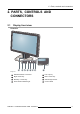
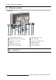
2. Parts, controls and connectors 2. PARTS, CONTROLS AND CONNECTORS 2.
2. Parts, controls and connectors 2.2 Display rear view Overview 1 2 3 4 5 6 7 8 9 10 11 12 Image 2-2 1 USB downstream connector 2 USB upstream connector 3 Ethernet connector (see note below) 4 DVI 1 video input 5 DisplayPort 1 video input 6 Connector compartment cover 7 Neck cover 8 Display stand cover 9 DisplayPort 2 video input 10 DVI 2 video input 11 +5 Vdc, 0.
3. Display installation 3. DISPLAY INSTALLATION Prior to installing your Coronis Fusion 10MP and connecting all necessary cables, make sure to have a suitable display controller physically installed in your computer. If you are using a Barco display controller, please consult the user guide delivered with it to do this. For a list of compatible display controllers, please refer to the latest version of the compatibility matrix available on myBarco.
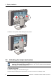
3. Display installation 2. Slide the cover upwards while holding the clips pressed. 3.2 Unlocking the height mechanism In the factory, the height-positioning system in the display stand is locked with a red hook to prevent damage during transportation. You’ll have to remove this hook before adjusting your display height position. To remove the hook: 1. Position the display with its rear side facing you. 2. While holding the display panel pushed down, pull out the red hook in the display stand.
3. Display installation 3. Keep the clip in the dedicated hole in case the display needs to be shipped later. To retain the hook for possible future transportation, insert the short, red end of the hook back into the stand of your display. 3.3 Adjusting the display position Now that the height-positioning system of your display is unlocked, you can adjust the display position. To adjust the display position 1. Tilt, swivel, raise and lower the display as desired.
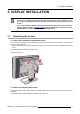
3. Display installation CAUTION: Do not try to pivot your display when attached to the stand. Trying to do so could cause serious damage to your display and its stand. 3.4 Connecting the signal cables To get access to the connectors, remove the connector compartment cover. See "Removing the covers", page 7 . Each side of your display can have a different video input connected (one side can have DVI connected while the other side has DisplayPort connected).
3. Display installation 3.5 Connecting the power cable To connect the power cable to the display: 1. Connect the supplied external DC power supply to the +24 VDC power input of your Coronis Fusion 10MP display. 2. Plug the other end of the external DC power supply into a grounded power outlet by means of the proper power cord delivered in the packaging. 3.6 Routing the cables To route the cables 1. Route all connected cables through the cable routing channel in the stand of your display. Tip: 3.
3. Display installation To re-attach the connector compartment cover 1. Slide the cover’s top in position and then push the cover’s bottom. You’ll hear a “click” sound of the cover’s clips when the connector compartment cover is in position. 3.8 VESA-mount installation WARNING: Never move a display attached to an arm by pulling or pushing the display itself. Instead, make sure that the arm is equipped with a VESA approved handle and use this to move the display.
3. Display installation Overview The panel, standard attached to a stand, is compatible with the VESA 100 mm standard. Thus, it can be used with an arm that is approved by VESA. This chapter shows you how to release the panel from the stand and how to attach it to an arm. If you’re not using an arm, you can skip this chapter. 1. Gently pull open both lower sides of the cover. 2. Slide the cover upwards while holding the lower sides pulled open. 3.
3. Display installation 4. Unscrew the four fixation screws fixing the panel to the stand. 5. Attach the panel firmly to the arm using 4 screws M4 x 10 mm. 3.9 First time starting up Overview You are now ready to start up your Coronis Fusion 10MP for the first time. 1. Switch on your Coronis Fusion 10MP as described in "Stand-by switching", page 16. 2. Turn on the computer connected to your display.
4. Daily operation 4. DAILY OPERATION 4.1 Recommendations for daily operation Optimize the lifetime of your display Enabling the Display Power Management System (DPMS) of your display will optimize its diagnostic lifetime by automatically switching off the backlight when the display is not used for a specified period of time. By default, DPMS is enabled on your display, but it also needs to be activated on your workstation. To do this, go to “Power Options Properties” in the “Control Panel”.
4. Daily operation Maximize quality assurance The ’MediCal QAWeb’ system offers online service for high-grade Quality Assurance, providing maximum diagnostic confidence and uptime. Barco recommends to install MediCal QAWeb Agent and apply the default QAWeb policy at least. This policy includes calibration on regular intervals. Connecting to MediCal QAWeb Server offers even more possibilities. Learn more and sign up for the free MediCal QAWeb Essential level at www.barco.com/healthcare/qa. 4.
4. Daily operation Switching on the display while it is in stand-by mode or vice versa can both be done by using the keys or by using the control wheel. To switch your display on using the keys: 1. Light up the keys indicator lights as previously described. 2. While the keys are light up, touch the Stand-by/Cancel key for approximately 2 seconds. As a result, the display will switch on and the power status indicator light is dimmed. To switch your display on using the control wheel: 1.
4. Daily operation How to bring up the OSD menus using the control wheel 1. If not already done so, switch on the display as previously described. 2. Shortly turn the control wheel. As a result, the OSD main menu comes up in the bottom right corner of the screen. If no further actions are taken within the following 90 seconds however, the OSD menu will disappear again. The OSD menu auto-exit function can be disabled in the OSD menu.
5. Advanced operation 5. ADVANCED OPERATION 5.1 OSD menu position About the OSD menu position By default, the OSD menu comes up in the bottom center position of the screen. This position can be modified however. There’s choice from a number of predefined positions. To change the position of the OSD menu: 1. Bring up the OSD main menu. 2. Navigate to the Configuration > User Interface > Menu menu. 3. Enter the Position submenu. 4. Select one of the available OSD menu positions and confirm. 5.
5. Advanced operation 5.4 Power status indicator light About the power status indicator light By default, when the display is switched on, the power status indicator light is dimmed. This behavior can be changed so that the power status indicator light will be blue when the display is switched on. When the display is in stand-by mode, the power status indicator light will always turn orange, even when the power status indicator light is disabled. To enable/disable the power status indicator light: 1.
5. Advanced operation 5.7 Keys sound About keys sound By default, the keys will make a “beep” sound on every touch. However, this sound can be disabled so that no sound will be heard when using the keys. To enable/disable the keys sound: 1. Bring up the OSD main menu. 2. Navigate to the Configuration > User Interface > Controls menu. 3. Enter the Sound submenu. 4. Select Enabled/Disabled as desired and confirm. 5.8 Ethernet over USB About Eth.
5. Advanced operation Enabling the USB endpoint is only recommended when you are using a non-Barco display controller. If you are using a Barco display controller, this communication will automatically be done over the connected video cable(s). To enable/disable USB: 1. Bring up the OSD main menu. 2. Navigate to the Configuration > Connectivity menu. 3. Enter the USB submenu. 4. Select Enabled/Disabled as desired and confirm. 5.
5. Advanced operation 5.12 Viewing modes About viewing modes The Coronis Fusion 10MP can be used in two viewing modes: Diagnostic This mode provides the full calibrated luminance and is intended for using the display for diagnostic purposes. In this mode, the luminance is reduced to approximately half of the luminance. This is intended for using the display with office applications such as word processing.
5. Advanced operation DICOM User Gamma 1.8 Gamma 2.2 DICOM (Digital Imaging and Communications in Medicine) is an international standard that was developed to improve the quality and communication of digital images in radiology. In short, the DICOM display function results in more visible grayscales in the images. Barco recommends selecting the DICOM display function for most medical viewing applications.
5. Advanced operation The American Association of Physicists in Medicine (AAPM) composed a list of pre-defined reading rooms.
5. Advanced operation 5.17 Embedded QA Overview • • • • • • About Embedded QA DICOM status report DICOM compliance check DICOM calibration Reset DICOM calibration DICOM error threshold 5.17.1 About Embedded QA About Embedded QA allows you to run a display calibration or compliance test directly from the display using the OSD menus described in the next sections. Embedded QA will use the front sensor / I-Guard to measure the necessary luminance levels for either a calibration or compliance test.
5. Advanced operation DICOM Calibration Status No calibration executed yet. Calibration executed. Current DICOM Settings Display function Ambient Light Compensation Reading room No other information is visible When the calibration is executed, the following extra information is shown: Backlight runtime elapsed since latest calibration, display function, ambient light compensation, reading room. Shows the current display function. Shows the ambient light compensation status.
5. Advanced operation 3. Enter the DICOM preferences submenu. 4. Select reset DICOM calibration to restore the original (not corrected) DICOM curve. 5.17.6 DICOM error threshold About DICOM error threshold The threshold to define the DICOM compliance can be modified in steps of 5% starting from 5 to 30%. When the maximum deviation is not bigger than the selected threshold, the compliance check will be OK. To set the DICOM error threshold: 1. Bring up the OSD main menu. 2.
5. Advanced operation Automatic One Image Source Two Image Sources In this mode, your display automatically detects the connected video input signals, attaches them to the correct display side and applies the correct video settings to it (resolution, video encoding mode, refresh rate,...). No video settings are available when this mode is selected. This mode is intended for displaying and manually configuring only one connected video input signal.
5. Advanced operation 5.21 Video encoding modes Your Coronis Fusion 10MP display automatically detects the connected video input signals and applies the correct video encoding settings. Manually selecting a video encoding mode is possible, but then your display’s image source selection mode should be set to allow this. Please refer to "Image source selection modes", page 28 to do this.
5. Advanced operation About grayscale conversion modes Grayscale conversion modes specify how color generated on the display controller is converted to grayscale in your display. The available grayscale conversion modes are: No Conversion Use Red Channel Use Green Channel Use Blue Channel Use All Channels This mode is intended for grayscale displays where gray is sent over the red channel. This mode is intended for grayscale displays where gray is sent over the green channel.
5. Advanced operation 5.24 Display info About display info Your display serial number, color type, native resolution, firmware versions, etc. are available in a dedicated submenu of the OSD menu. To retrieve info about your display: 1. Bring up the OSD main menu. 2. Navigate to the About this Display menu to make the information visible on the screen. 5.
6. Repackaging instructions 6. REPACKAGING INSTRUCTIONS WARNING: Before repacking the display, follow the instruction to replace the protection buffer to prevent damage to the display.
6.
6. Repackaging instructions 6.1 Repacking your display How to repack your display 1. Place the empty box on a stable surface. 2. Slide the system CD, documentation CD and user guide in the dedicated bag attached at the inside of the box. 3. Place the bottom buffer in the box. 4. Put the power supply in the dedicated cavity of the bottom buffer. 5. Put the Coronis Fusion 10MP display in its original bag and place it in the box with its panel facing downwards. 6. Put the top buffer on top of the display. 7.
6.
7. Cleaning your display 7. CLEANING YOUR DISPLAY 7.1 Cleaning instructions To clean the display Clean the display using a sponge, cleaning cloth or soft tissue, lightly moistened with a recognized cleaning product for medical equipment. Read and follow all label instructions on the cleaning product. In case of doubt about a certain cleaning product, use plain water.
7.
8. Important information 8. IMPORTANT INFORMATION 8.1 Safety information General recommendations Read the safety and operating instructions before operating the device. Retain safety and operating instructions for future reference. Adhere to all warnings on the device and in the operating instructions manual. Follow all instructions for operation and use. Electrical Shock or Fire Hazard To prevent electric shock or fire hazard, do not remove cover. No serviceable parts inside.
8. Important information To fully disengage the power to the device, please disconnect the power cord from the AC inlet. Power cords: • • • • • Utilize a UL-listed detachable power cord, 3-wire, type SJ or equivalent, 18 AWG min., rated 250 V min., provided with a hospital-grade type plug 5-15P configuration for 120V application, or 6-15P for 240V application. Do not overload wall outlets and extension cords as this may result in fire or electric shock. Mains lead protection (U.S.
8. Important information waste. Please dispose of your waste equipment by handing it over to a designated collection point for the recycling of waste electrical and electronic equipment. To prevent possible harm to the environment or human health from uncontrolled waste disposal, please separate these items from other types of waste and recycle them responsibly to promote the sustainable reuse of material resources.
8. Important information 零件项目(名称) 有毒有害物质或元素 Component name Hazardous substances and elements 汞 六价铬 铅 镉 Pb Hg Cd Cr6+ 散热片(器) o o o o 多溴联苯 多溴二苯 醚 PBB PBDE o o Heatsinks 电源供应器 x o o o o o Power Supply Unit 风扇 o o o o o o Fan 文件说明书 o o o o o o Paper Manuals 光盘说明书 o o o o o o CD manual O: 表示该有毒有害物质在该部件所有均质材料中的含量均在 SJ/T 11363-2006 标准规定的限量要求以下.
8. Important information Caution (USA): Federal law restricts this device to sale by or on the order of a physician. (Details & exemptions are in the Code of Federal Regulations Title 21, 801 Part D). FCC class B This device complies with Part 15 of the FCC Rules. Operation is subject to the following two conditions: (1) this device may not cause harmful interference, and (2) this device must accept any interference received, including interference that may cause undesired operation.
8. Important information Emissions test Compliance RF emissions Class B CISPR 11 Harmonic emissions Class D IEC 61000-3-2 Voltage fluctuations/ flicker emissions Electromagnetic environment – Guidance The Coronis Fusion 10MP is suitable for use in all establishments, including domestic establishments and those directly connected to the public low-voltage power supply network that supplies buildings used for domestic purposes.
8. Important information Immunity test Electromagnetic environment – Test levels guidance Voltage dips, short < 5% U T 1(> 95% dip in < 5% U T (> 95% dip in Mains power quality interruptions and voltage U T) for 0.5 cycle should by that of a typical U T) for 0.5 cycle variations on power commercial or hospital 40% U T (60% dip in U T) 40% U T (60% dip in U T) supply input lines environment.
8. Important information Immunity test IEC 60601 Compliance level Test levels Electromagnetic environment – guidance than the compliance level in each frequency range.4 Interference may occur in the vicinity of equipment marked with symbol: At 80 MHz and 800 MHz, the higher frequency range applies. These guidelines may not apply in all situations. Electromagnetic propagation is affected by absorption and reflection from structures, objects and people.
8. Important information These guidelines may not apply in all situations. Electromagnetic propagation is affected by absorption and reflection form structures, object and people. 8.
8. Important information Indicates the DisplayPort connectors on the device Indicates the manufacturing date Indicates the temperature limitations6 for the device to safely operate within specs Indicates the device serial no.
8. Important information Barco Inc. and the licensee. No other use, duplication, or disclosure of a Barco software product, in any form, is authorized. The specifications of Barco products are subject to change without notice. Trademarks All trademarks and registered trademarks are property of their respective owners. Copyright notice This document is copyrighted. All rights are reserved.
8. Important information DICOM calibrated luminance (ULT off) Contrast ratio (typical) 7 Response time (Tr + Tf) 500 cd/m² (panel typical) 950:1 (panel typical) 35 ms Scanning frequency (H; V) Housing color 30-150 kHz; 15-80 Hz Video input signals DVI-D Dual Link (2x) / DisplayPort (2x) NA Video inout terminals USB ports USB standard Black / Silver 1 upstream (endpoint), 3 downstream 2.
8. Important information Supplied accessories User Guide Quick Installation Sheet Video cables (2 x DVI Dual Link + 2 x DisplayPort) Main cables (UK, European (CEBEC/KEMA), USA (UL/ CSA; adaptor plug NEMA 5-15P), Chinese (CCC)) USB 2.0 cable External power supply 8.