DATA 708 R9002129 INSTALLATION MANUAL
BARCO PROJECTION SYSTEMS DATA 708 R9002129 INSTALLATION MANUAL Date : 260597 Art. No.
Due to constant research, the information in this manual is subject to change without notice. Produced by BARCO NV, May 1997. All rights reserved. Trademarks are the rights of their respective owners.
Table of Contents i TABLE OF CONTENTS WARNINGS .................................................................................................................................................................................... SAFETY INSTRUCTIONS ............................................................................................................................................................... On safety ...........................................................................................
Table of Contents i-2 5975987A BARCODATA 708 260597
Safety Instructions 1 SAFETY INSTRUCTIONS Notice on Safety This equipment is built in accordance with the requirements of the international safety standards EN60950, UL 1950 and CSA C22.2 No.950, which are the safety standards of information technology equipment including electrical business equipment.
Safety Instructions Power cord with ANSI 73.11 plug: The wires of the power cord are colored in accordance with the following code. Green/yellow: ground White: neutral Black: line (live) d. If the product does not operate normally when the operating instructions are followed.
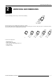
Unpacking and Dimensions 2 UNPACKING AND DIMENSIONS Unpacking To open de banding, pull on the clip as shown in the first drawing. Take the projector out of its shipping carton and place it on a table. Save the original shipping carton and packing material, they will come in handy if you ever have to ship your projector. For maximum protection, repack your projector as it was originally packed at the factory. Contents of the shipped box : - 1 BARCODATA 708.
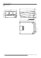
Unpacking and Dimensions Projector dimensions (mm) 2-2 5975987A BARCODATA 708 260597
Installation Guidelines 3 INSTALLATION GUIDELINES Installation guidelines Careful consideration of things such as image size, ambient light level, projector placement and type of screen to use are critical to the optimum use of the projection system. * Environment Do not install the projection system in a site near heat sources such as radiators or air ducts, or in a place subject to direct sunlight, excessive dust or humidity.
Installation Guidelines * Where to install the projector? To indicate a correct installation position it is necessary to know the distance : - projector - ceiling - projector - screen ceiling PD B CD A projector To find this correct position for the projector, equipped with HD145 lenses, formulas are given in the next paragraph. screen Abbreviations used on drawing and diagrams on next pages Front view B = Distance between ceiling and top of the screen.
Installation Set Up 4 INSTALLATION SET UP Access to controls Opening procedure : During the projector set up and installation it is necessary to open the top cover. To gain access, procede as follow : *Turn both lock screws with a screwdriver or a coin counter clockwise. * Lift up and pivot the top cover. * Support the top cover with the hand, no support is incorporated. During some installations it will become handy to remove the top cover totally.
Installation Set Up Scan adaptation The scanning can be switch by turning the Horizontal and Vertical scan connectors and the convergence connectors. To change the scanning, it is necessary to open the projector top cover and to rotate the chassis. For opening the projector's top cover, see Getting access to controls. WARNING TURN OFF PROJECTOR AND UNPLUG THE POWER CORD BEFORE CHANGING THE SCAN DIRECTION. Gaining access to the scan connectors and the convergence connectors.
Installation Set Up A : Horizontal scan inversion Three connectors are used, one for each horizontal deflection coil. When changing the horizontal scan, insure that all three connectors are set in the same position. See position of the connectors for the corresponding projector configuration. Front / Table Front / Ceiling Rear / Table Rear / Ceiling Horizont al scan connectors Vertical scan connectors B : Vertical scan inversion Three connectors are used, one for each vertical deflection coil.
Installation Set Up 4-4 5975987A BARCODATA 708 260597
Projector Set Up 5 PROJECTOR SET UP strap Projector Set Up The strap on the CPU unit allow a set up of the password mode.
Projector Set Up 5-2 5975987A BARCODATA 708 260597
Power Connection 6 POWER CONNECTION Power (mains) cord connection Use the supplied power cord to connect your projector to the wall outlet. Plug the female power connector into the male connector at the front of the projector.
Power Connection 6-2 5975987A BARCODATA 708 260597
Installation Adjustments 7 INSTALLATION ADJUSTMENTS Entering the adjustment mode Press ADJUST to enter the adjustment mode.
Installation Adjustments Overview flow chart installation mode. OPTICAL LENS FOCUSING SCHEIMPFLUG ADJUSTMENT 1. LOOSEN THE NUT ON THE REAR OF THE XXXX LENS, ROTATE THE LENS BARREL TO FOCUS THE CENTER OF THE IMAGE, THEN TIGHTEN THE NUT 2. LOOSEN THE NUT ON THE FRONT OF THE XXXX LENS AND ROTATE THE FRONT SECTION OF THE LENS TO FOCUS THE CORNERS OF THE IMAGE, THEN TIGHTEN THE NUT. LOOSEN THE 4 LENS MOUNTING NUTS ON EACH LENS, UNTIL THE TAG OF EACH SCHEIMPFLUG RING CAN BE MOVED TO ITS DESIRED POSITION (1.
Installation Adjustments Push the control disk up or down to highlight "Installation" and press ENTER. ADJUSTMENT MODE ENTER continues displaying a WARNING. EXIT returns to operational mode. ADJUST returns to operational mode. Select a path from below: GUIDED RANDOM ACCESS INSTALLATION SERVICE IRIS source 1 Select with or then to return A warning will be displayed on the screen. If you are qualified installation or service personnel, press ENTER to start up the installation mode.
Installation Adjustments Scheimpfug adjustment The scheimpfug correction can be adjusted separately for the three tubes within 3 ranges: range 1 : 1.4 m (55") to 1.9 m (75"), optimum screen width 1.4 m (55") range 2 : 1.9 m (75") to 3.2 m (126"), optimum screen width 2.4 m (94") range 3 : 3.2 m (126") to 6 m (236"), optimum screen width 4 m (157") A correct scheimpfug setting gives the possibility to focus the lenses for a sharp image in all screen areas. range 1 min. SW : 1.40 m (55") max. SW : 1.
Installation Adjustments Optical lens focusing The optical focusing procedure is performed separately for each lens. The appropriate CRT will be switched on as the user proceeds through the optical focusing adjustment sequence. Each lens has two focus adjustment points, one at the rear of the lens and one at the front. The center of the projected image is focused by loosening the wing nut at the rear end of the lens and rotating the lens barrel until the center of the image is clearly focused.
Installation Adjustments Raster centering The raster must be centered on the CRT screen surface of each tube, therefore, it is necessary to look into the lenses. Caution : To avoid eye discomfort while performing these adjustments, reduce the contrast and gradually increase the brightness level until the raster becomes visible behind the image. Warning : In order to ensure maximum CRT longevity and to avoid CRT damage, do not shift the raster outside the phosphor area of the CRT.
Installation Adjustments CRT projection angle adjustment The projection angle of the red and blue CRT's is dependent on the desired size of the projected image. If the centers of green, blue and red do not coincide, the CRT projection angle must be adjusted. Never try to correct this misalignment with the shift correction or the static convergence controls. These controls may only be applied to correct small errors which cannot be corrected by the CRT angle adjustment.
Installation Adjustments A' A B B' C' C B B' C' C D D' Screws A, B, C and D (M4) : upper fixation latch. nutdriver 7mm. Screw A', B', C' and D' (M4) : lower fixation latch. nutdriver 7mm. A' A Loosen the four hexagon screws A, A', B and B', upper and lower fixation latch. These screws fasten the cooling house of the red tube. Pivot the red CRT until the center of the red image coincides with the center of the green image. If the angle of the red CRT is corrected, tighten the four bolts.
Installation Adjustments After finishing the installation adjustments procedure, the 'Path selection' returns on the screen. You are now able to start the alignment procedure for the projector. You have the choice between: - Guided Adjustment Procedure - Random Access Adjustment Procedure The result of both procedures will be the same. More explanation about both procedures is given in the owners manual. The following paragraph gives an overview of the image corrections.
Installation Adjustments 7-10 5975987A BARCODATA 708 260597
G2 Adjustment A G2 ADJUSTMENT G2 adjustment Enter the adjustment mode by pressing ADJUST and highlight Service. Press ENTER to start up the service mode. ADJUSTMENT MODE Select a path from below: GUIDED RANDOM ACCESS INSTALLATION SERVICE IRIS source 1 Highlight 'Common settings' and press ENTER. Select with or then to return ENTER starts up the Common settings menu. EXIT returns to the adjustment mode menu.
G2 Adjustment A green LED for each color is mounted on the driver board, below the CRT's. When selecting the G2 adjustment menu, these green LEDs must be out. If not, follow the procedure to adjust the G2 : - Loosen the retaining screws of the upper electronic chassis and pivot it to the lenses. Loosen screws and move the cover plate to the left to access the G2 controls. Cover the G2 controls again after alignment.
Form Approved Bureau Budget No. 45-R0338 MATERIAL SAFETY DATA SHEET MANUFACTURER'S NAME AND FSCM (Federal Supply Code for Manufacturer's) BARCO N.V. EMERGENCY PHONE NO.
SECTION V HEALT HAZARD DATA TRESHOLD LIMIT VALUE EFFECTS OF OVEREXPOSURE EMERGENCY AND FIRST AID PROCEDURES STABILITY SECTION VI REACTIVITY DATA 100ppm CONDITIONS TO AVOID UNSTABLE STABLE X INCOMPATABILITY (Materials to avoid) HAZARDOUS DECOMPOSITION PRODUCTS HAZARDOUS POLYMERIZATION MAY OCCUR X CONDITIONS TO AVOID WILL NOT OCCUR SECTION IX SPECIAL PRECAUTIONS SECTION VIII - SPECIAL PROTECTION INFORMATION SECTION VII SPILL OR LEAK PROCEDURES STEPS TO BE TAKEN IN CASE MATERIAL IS RELEASED