MGP D5 User Guide
B4100515 - 00 October 2004 www.barco.
User Guide TABLE OF CONTENTS TABLE OF CONTENTS INTRODUCTION ..................................................................................... 4 SAFETY & WARNINGS ........................................................................... 5 OVERVIEW............................................................................................. 9 KEYPAD ............................................................................................... 10 STATUS .................................................
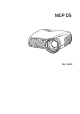
INTRODUCTION User Guide INTRODUCTION This digital projector is designed with the latest state-of-the-art technologies in illumination, imaging, optics, electronics, thermal and industrial design in order to serve traditional as well as novel imaging applications across a variety of markets, offering features such as: • 1400x1050 pixel SXGA+ DLP™ technology • Single chip DMD™ with DarkChip2™ technology by Texas Instruments® • HIGH CONTRAST for vibrant colors and deep blacks • HIGH RESOLUTION for unpreceden
User Guide SAFETY & WARNINGS SAFETY & WARNINGS This user guide contains important information about safety precautions and the set-up and use of the projector. Please read the manual carefully before you operate the projector. SAFETY This device complies with relevant safety regulations for data processing equipment for use in an office environment. Before using the projector for the first time, please read the safety instructions thoroughly.
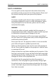
SAFETY & WARNINGS User Guide Only place the projector on a stable surface, or mount it securely using an approved ceiling-mount. Do not drop the projector. Always operate the projector horizontally, within the range of the adjustable rear feet. Operating the unit in other positions may reduce lamp life significantly, and may lead to overheating, resulting in malfunctioning. Always allow ample airflow through the projector. Never block any of the air vents. Never cover the unit in any way while running.
User Guide SAFETY & WARNINGS INFORMATION AND WARNING ABOUT POTENTIAL HEALTH ISSUES RELATED TO MERCURY VAPOR This projector is using an extremely bright UHP™ lamp for illumination to attain the desired high brightness image. This technology is similar to other high-pressure discharge lamps that are extensively used in cars, street lights and other lighting appliances today. These lamps, like fluorescent lighting, contain small amounts of mercury.
SAFETY & WARNINGS User Guide sensation in the lungs, coughing, nausea, vomiting and diarrhea. Children and fetuses are particularly sensitive to the harmful effects of metallic mercury to the nervous system. Seek medical attention if any of the above symptoms are experienced or if other unusual conditions are experienced following lamp rupture. REMOTE CONTROL WARNING Laser radiation class II product; wavelength 670nm; maximum output 1 mW.
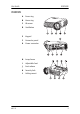
User Guide OVERVIEW OVERVIEW MGP D5 A Focus ring B Zoom ring C IR sensor D Ventilation E Keypad F Connector panel G Power connector H Lamp house I Adjustable foot J Foot release K Security lock L Ceiling mount 9
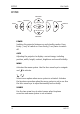
KEYPAD User Guide KEYPAD VOLUME + SOURCE MENU SOURCE POWER AUTO STATUS VOLUME – POWER Switches the projector between on and standby modes. Press firmly (1 sec) to switch on. Press firmly (1 sec) twice to switch off. AUTO Adjusting the projector to display a correct image, including position, width, height, contrast, brightness and overall stability. MENU Activates the menu system. Use the four arrow keys to navigate and to activate. / Select menu option when menu system is activated.
User Guide KEYPAD VOLUME Use the two arrow keys to adjust the sound volume. STATUS This is an indicator light, not a key. Do not push. It indicates the current projector status. See STATUS chapter for detail.
STATUS User Guide STATUS POWER STATUS PERMANENT GREEN LIGHT The projector is turned on and in normal operation. PERMANENT YELLOW LIGHT The unit is in standby mode; no source(s) connected, or the source(s) connected are inactive or switched off, thereby activating the power-save function (DPMS). You may enable or disable the power save function in the SET UP sub menu, DPMS on or off. FLASHING YELLOW LIGHT Please wait. The yellow light will flash a period after power cord is connected (10-15 sec.
User Guide REMOTE CONTROL REMOTE CONTROL The remote control allows flexible access to the projector settings, either through direct keys, or through the menu system. The remote control can be used to emulate the computer mouse through the USB interface. POWER Switches the projector between on and standby modes. AUTO Adjusting the projector to display a correct image, including position, width, height, contrast, brightness and overall stability. OSD Toggle On Screen Display (OSD) feedback of and off.
REMOTE CONTROL User Guide YPbPr Selects component video input DVI Selects the DVI input VGA 1 Selects the VGA 1 input VGA 2 Selects the VGA 2 input STILL Toggles between live and still (frozen) image AV MUTE Toggles between live and no (muted) image BRIGHT Adjusts image brightness from dark to bright CONTRAST Adjusts the image contrast from soft to hard COLOR Adjusts the color of the image from pale to saturated VOLUME Adjusts the sound volume ASPECT Cycles through the aspect ratios available with the cur
User Guide REMOTE CONTROL TRACKBALL When USB cable is connected between PC and projector, the trackball is used to move the mouse pointer when not in the menu. Use the trackball to navigate between options when in the menu. LEFT/SELECT Use as mouse LEFT key when not in the menu. Use as SELECT key when in the menu RIGHT Use as mouse RIGHT key LASER Activates the built-in laser pointer. CAUTION! Do not point laser beam at people. Do not stare into laser beam.
CONNECTOR PANEL User Guide CONNECTOR PANEL 16 A YPbPr: Used for high quality video reproduction. B S-VIDEO: Used for improved quality video. C C-VIDEO: Used for standard video quality. D DVI-D - Digital RGB: For a low noise computer and video image. E Monitor VGA out: Allows for connection to local VGA monitor or daisy-chaining of several projectors using VGA. Works with VGA inputs only. F VGA - Analog RGB 1-2: The standard analog computer graphics interface.
User Guide MGP D5 CONNECTOR PANEL K USB - interface: Allows for computer mouse control. L LAN: Provides access to control and monitoring over a Local Area Network. M Mains power connector: Use only three-prong, grounded power cord.
SET UP VIDEO User Guide SET UP VIDEO Before setting-up, switch off all equipment. Three video sources may be connected, using the YPbPr (component), S-VIDEO (super video) and VIDEO (composite video) inputs. Component video will display more detailed images. Composite video yields images with less detail. In addition, the DVI-D input can be used with video sources (DVD player fitted with an HDCPTM compliant DVI or HDMI connector) for a pure digital connection. Connect the power cord.
User Guide SETUP COMPUTER SETUP COMPUTER Before setting-up, switch off all equipment. The projector may be connected to up to three computer sources simultaneously, using the VGA and DVI inputs. The VGA interface is analog and may cause some noise in the projected image, depending on the signal quality from the VGA graphics card in the computer. The DVI (Digital Visual Interface) interface is all-digital and will yield a projected image with very low noise.
IMAGE ADJUSTMENTS User Guide IMAGE ADJUSTMENTS Turn the FOCUS (A) and ZOOM (B) rings on the projection lens to get a correctly sized and focused image. If the desired image size is not achieved by zooming, relocate the unit nearer or farther away from the projection screen and refocus. To adjust the projected image to the desired height on the screen, eject the front foot (C) by pressing the release button (D), and adjust the angle to the right position.
User Guide CEILING MOUNT (option) CEILING MOUNT (option) CEILING MOUNT KIT Please refer to the “MSP-BAR034” installation instructions included in the ceiling mount kit package. The projector is provided with 3 threaded inserts (L) to attach the UPA interface bracket of the ceiling mount kit. CEILING MOUNT COVER The auxiliary cable cover can be mounted on the projector to conceal the interface cables and power cord when the unit is ceiling mounted.
CEILING MOUNT (option) 22 User Guide MGP D5
User Guide USING THE PROJECTOR USING THE PROJECTOR After setting-up, switch on all equipment. To switch the projector on, firmly press the POWER button on the keypad or the remote control. The STATUS indicator will turn from yellow to green when the unit is switched on. If the STATUS indicator is flashing yellow, please wait until it turns permanent yellow. When only one source is connected, the projector will autodetect that source.
USING THE PROJECTOR User Guide want to switch off the unit). The STATUS indicator will turn from green to flashing yellow, then yellow when switched off. You may not switch the unit on while the STATUS indicator is flashing yellow. Please wait until the indicator is permanent yellow.
User Guide MENU SYSTEM MENU SYSTEM The menu system gives access to a multitude of image and system controls. The menu system is structured through a top menu and several sub menus. The sub menus may vary depending on the actual source selected. Also, some functions are not available when the DICOM display curve is selected. When accessing the menu system, you will enter at the position you left last time you were using the menu system.
MENU SYSTEM User Guide PICTURE SUB MENU S-VIDEO/COMPOSITE VIDEO brightness 50 contrast 50 color 50 tint 50 sharpness 3 aspect fill 16:9 YPbPr (progressive) brightness 50 contrast 50 color 50 hue 50 space sharpness SMPT REC601 REC709 3 aspect fill 16:9 YPbPr (interlaced) brightness 50 contrast 50 color 50 tint 50 sharpness 3 aspect fill 16:9 VGA brightness 40 contrast 70 sharpness 3 aspect 26 } Not available in DICOM mode fill aspect ratio MGP D5
User Guide MENU SYSTEM DVI brightness 50 contrast 50 sharpness 3 aspect } Not available in DICOM mode fill aspect ratio brightness Adjusts the image brightness. A higher setting will increase the brightness, a lower setting will decrease the brightness of the image. contrast Controls the contrast of the image. A higher setting will yield a 'harder' image with larger difference between shades, while a low setting will produce a 'softer' image with less difference between shades.
MENU SYSTEM User Guide aspect Selects image format. An image may be displayed in various aspect ratios. This function is used when displaying source formats that differ from the projectors native display format. space Defines the color standard used for component video so that the image is displayed with the proper characteristics.
User Guide MENU SYSTEM lamp runtime The total time the lamp has been operating since the projector was produced or the lamp was replaced, if the lamp counter was reset after replacement. DICOM Allows to select a DICOM display function, which optimizes the projector to the DICOM standard.
MENU SYSTEM User Guide YPbPr (progressive) H position 50 V position 50 Phase 4 864 frequency color temp 6500 7300 9300 custom custom color YPbPr (interlaced) H position 50 V position 50 color temp 6500 7300 9300 custom custom color video format auto NTSC PAL SECAM video type DVD VCR VGA H position 50 V position 50 phase frequency 4 1688 color temp 6500 7300 9300 custom custom color full auto image -> Always “custom” in DICOM mode -> Not available in DICOM mode press DVI color tem
User Guide MENU SYSTEM phase Adjust for stable image. A jittery image may appear with certain VGA sources. You may also press the AUTO button on the keypad or remote control to optimize. frequency Adjust image width. An incorrect setting may produce vertical, unstable bands in the image, and parts of the image may not be displayed on screen. Push the AUTO button to find a correct setting, or manually adjust the frequency until the vertical bands disappear. color temp Changes the color temperature.
MENU SYSTEM User Guide full auto image Adjusts h and v position, phase and frequency automatically. Important: you must perform the full auto image function on a good test pattern. Otherwise, the image may not be correctly adjusted. Therefore, to perform the full auto image function correctly, run the calibration wizard in the TheaterWatch software application.
User Guide MENU SYSTEM SET UP SUB MENU FOR ALL keystone V 0 keystone H 0 DPMS on off source scan on off orientation desktop front OSD language RGB Video off keystone V Adjust vertical keystone correction. Compensates for the geometrical distortion of the projected image resulting from tilting the projector to shoot higher up on the wall. keystone H Adjust horizontal keystone correction.
MENU SYSTEM User Guide orientation Select between desktop front, desktop rear, ceiling front and ceiling rear mode. The image will be flipped and reversed accordingly. OSD Select where to have the On Screen Display language Select between languages RGB video Selects RGB video on the component video input (YPbPr). Requires composite sync connected to the composite video input.
User Guide MENU SYSTEM SYSTEM INFORMATION system information source: s-video brightness: 50 format: 576p PAL contrast: 47 mode: 69 color: 40 software: 0034-01.06 sharpness: 3 lamp remaining: 1999:44 gamma: film 1 black level: 0 color temp: 6500K White boost: 0 MAC: 00-00-00-00-00-00 IP address: 0.0.0.0 subnet: 0.0.0.0 gateway: 0.0.0.
MENU SYSTEM User Guide service menu For service personnel only. A special service code is needed to access internal calibration controls and status information. Not accessible to the user. test image Applies a fixed test image for set-up purposes CONTROL SUB MENU FOR ALL RS232 mode auto fixed 232 RS232 Address 232 RS232 Fixed 1 232 baudrate 19200 Mode Selects between RS232, RIMI (internal) and LAN control modes. The projector can be controlled by only one of the modes at a time.
User Guide MOUSE CONTROL MOUSE CONTROL You may control the computer mouse functions using the remote control. In order to enable this function, connect a USB cable between the computer and the projector. Ensure that the PC has an operating system that supports USB (Windows™ 98 2nd edition or newer). As long as the menu system on the projector is not activated, the tracker ball on the remote control will now emulate the mouse movements.
RS 232 AND LAN CONTROL User Guide RS 232 AND LAN CONTROL RS 232 You may control and monitor the projector remotely through the serial RS232 control interface. The RS232 protocol is a binary protocol where each command is a series of 32 bytes in one packet. The protocol allows for both SET and GET operations. To utilize GET operations the host needs a routine for receiving and interpreting incoming packets.
User Guide TROUBLESHOOTING TROUBLESHOOTING NO IMAGE No connection: Check if all connections are properly made. Source off: Check if the equipment is powered on. Lamp dead: The lamp may need replacement. Check the LAMP TIME in the UTILITIES sub menu. Source hibernated: Engage the source to display and active image. Notebook external screen: Different notebook PC's use different combinations of keystrokes to enable the external graphics port. Source scan off: Check SOURCE SCAN in the SET UP sub menu.
TROUBLESHOOTING User Guide UNSHARP IMAGE Keystone correction may have been activated inadvertently: compressing parts of the image that affect the display of fine-line graphics, text and other images of high resolution. Source resolution is different from projectors native resolution: The projector will automatically scale and resize the input format to its native resolution. Use a different scaling factor in the PICTURE sub menu, ASPECT. You may also adjust the SHARPNESS.
User Guide MAINTENANCE MAINTENANCE The projector may from time to time need cleaning. Never open the unit, as this will void any warranties. Refer service and repair to qualified personnel only. The projector is using a lamp that has a limited life time. Please refer to the LAMP CHANGE section below for further details. Only the exterior of the unit may be cleaned. Use a damp cloth.
MAINTENANCE User Guide HEAVY DUTY AND CONTINOUS USE The projector contains moving parts (such as cooling fans) that have limited life-expectancies. When the projector has been used for 7 500 hours, and when the unit is applied to mission-critical use, it is recommended that the projector is given preventive maintenance by a qualified service person. This will help ensure long term stable operation.
User Guide LAMP CHANGE LAMP CHANGE The STATUS lamp on the keypad will turn red when the lamp life expires. In addition, a message will appear on the screen: “LAMP LIFE TIME HAS EXPIRED! Please change lamp!” POWER STATUS Change the lamp when lifetime expires. Always replace lamp with the same type and rating. Always disconnect the power cord and wait until the projector has cooled down (60 minutes) before opening the lamp cover (B). Release the screw (A). Remove the lamp cover (B).
LAMP CHANGE User Guide Remove the lamp house (E). Replace with a new lamp in reverse order. Replace the lamp house (E) and tighten the screws (C). Fold the handle (D) in place.
User Guide LAMP CHANGE Replace the lamp cover (B) and tighten the screw (A). In the “utilities” sub menu, reset the lamp timer. press system information OSD on off OSD timeout 50 seconds OSD background opaque translucent reset press lamp reset press service menu test image press hide show WARNING Be careful not to touch the protective glass when replacing the lamp house, this may cause the protective glass to overheat and break while in use.
SERVICE INFORMATION User Guide SERVICE INFORMATION This product contains no user serviceable parts. If the product fails to function as expected, please first check that all connections are properly made, and that the power cord is properly connected. Please check that the projector as well as the video and computer sources are all switched on. Cables and cords may break over time. Try to change cables and cords, in case there is a bad or intermittent connection.
User Guide TECHNICAL DATA TECHNICAL DATA Resolution 1400 x 1050 (native) SXGA+ Display technology Single chip DLP™ technology by Texas Instruments Display device LVDS DMD™ with DarkChip2™ technology Computer Compatibility UXGA, SXGA+, SXGA, XGA, SVGA, VGA PC, MAC, SGI and other workstations RGBHV, RGBS, RGsB Video Compatibility HDTV (1080i, 720p, 576i/p, 480i/p) NTSC, NTSC 4.43, PAL, PAL-M, PAL-N, SECAM.
TECHNICAL DATA 48 User Guide Lamp Life 2000 hrs (typ) to 50% brightness @ 250W 4000 hrs (typ) to 50% brightness @ 200W Noise level 28 dB (typ), 32 dB (max) @ 20°C/68°F, sea level Dimensions 244 x 278 x 88 mm / 9.6" x 10.9" x 3.5", excluding lens Weight 3.4 kg/7.5 lbs Inputs 2 VGA 15 pin female HD-DSUB analog RGBHV 1 DVI-D female digital RGB 1 Component video female 3 x RCA/phono 1 S-video female 4 pin mini-DIN 1 C-video female RCA/phono 2 Audio 3.
User Guide Humidity storage TECHNICAL DATA 10-95% RH, non-condensing Specifications subject to change without prior notice. All values may vary up to +/- 20%.
7.50 6.75 6.00 5.25 4.50 3.75 3.00 2.25 1.50 0.75 0 1.98 1.78 1.58 1.39 1.19 0.99 0.79 0.59 0.40 0.20 0.0 0.60 0.54 0.48 0.42 0.36 0.30 0.24 0.18 0.12 0.06 0 Accuracy: +/- 5% m 0 2.48 4.95 7.43 9.90 12.38 14.85 17.33 19.80 22.28 24.75 ft Image height ft m Offset (8%) 0 0 3.30 1.00 Throw ratios SX+, zoom and fixed lenses 6.60 2.00 9.90 3.00 13.20 4.00 1 16.50 1 .7 0: 1 19.80 6.00 23.10 7.00 1 .2 : ns 2 mle Zoo ns ml e Zoo 5.
User Guide TECHNICAL DATA G/Y S-Video PHONO/RCA FEMALE 4 PIN MINI DIN FEMALE 1 GND 2 GND 3 Luma 4 Chroma STEM GREEN: G/Y SHIELD: GND B/Pb Composite Video PHONO/RCA FEMALE PHONO/RCA FEMALE STEM BLUE: B/Pb SHIELD: GND STEM YELLOW: Composite SHIELD: GND R/Pr PHONO/RCA FEMALE STEM RED: R/Pr SHIELD: GND MGP D5 51
TECHNICAL DATA 52 User Guide Computer DVI Computer VGA 1 DVI-D 15 HIGH DENSITY DSUB FEMALE 1 2 3 4 5 6 7 8 9 10 11 12 13 14 1 2 3 4 5 6 7 8 9 10 11 12 13 14 15 TMDS Data 2TMDS Data 2+ TMDS Data 2/4 Shield Not used Not used DDC Clock DDC Data NC TMDS Data 1TMDS Data 1+ TMDS Data 1/3 Shield Not used Not used +5V Power Analog R in Analog G in Analog B in AGND AGND Analog R GND in Analog G GND in Analog B GND in Reserved Sync GND in AGND DDC/SDA H Sync in V Sync in DDC/SCL Monitor VGA Computer VGA 2
User Guide TECHNICAL DATA RS-232 in RS-232 out 9 PIN DSUB FEMALE 9 PIN DSUB MALE 1 2 3 4 5 6 7 8 1 2 3 4 5 6 7 8 NC RXD TXD NC GND NC NC NC Audio out RC in Black 3.5 mm mini jack 3.5 mm stereo mini jack TIP: R STIM: L RING: GND TIP: 5V DC RING: SIGNAL STEM: GND Audio in 1 Audio in 1 Black 3.5 mm mini jack Black 3.
DECLARATIONS User Guide DECLARATIONS FCC This equipment has been tested and found to comply with the limits for a Class A digital device, pursuant to part 15 of the FCC Rules. These limits are designed to provide reasonable protection against harmful interference when the equipment is operated in a commercial environment.