auJTMM rëÉêÛë=dìáÇÉ • • Manual #: 26-0601000-00 Revision: 02
auJTMM=√=rëÉêÛë=dìáÇÉ `çéóêáÖÜí © Barco. May 19, 2010 All rights reserved. No part of this document may be copied, reproduced or translated. It shall not otherwise be recorded, transmitted or stored in a retrieval system without the prior written consent of Barco. kçíáÅÉ Barco provides this manual “as is” without warranty of any kind, either expressed or implied, including but not limited to the implied warranties or merchantability and fitness for a particular purpose.
agreed upon in the contract, all guarantee claims of the purchaser will be rendered invalid. Not included in the guarantee coverage are system failures which are attributed to programs or special electronic circuitry provided by the purchaser, e.g. interfaces. Normal wear as well as normal maintenance are not subject to the guarantee provided by Barco either. The environmental conditions as well as the servicing and maintenance regulations specified in this manual must be complied with by the customer.
léÉê~íçêë=p~ÑÉíó=pìãã~êó The general safety information in this summary is for operating personnel. aç=kçí=oÉãçîÉ=`çîÉêë=çê=m~åÉäë There are no user-serviceable parts within the unit. Removal of the top cover will expose dangerous voltages. To avoid personal injury, do not remove the top cover. Do not operate the unit without the cover installed.
qÉêãë=få=qÜáë=j~åì~ä=~åÇ=bèìáéãÉåí=j~êâáåÖ= t^okfkd Highlights an operating procedure, practice, condition, statement, etc., which, if not strictly observed, could result in injury to or death of personnel. Note Highlights an essential operating procedure, condition or statement. `^rqflk The exclamation point within an equilateral triangle is intended to alert the user to the presence of important operating and maintenance (servicing) instructions in the literature accompanying the appliance.
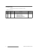
`Ü~åÖÉ=eáëíçêó The table below lists the changes to the DX-700 User’s Guide. Table 0-1.
q~ÄäÉ=çÑ=`çåíÉåíë `Ü~éíÉê=N fåíêçÇìÅíáçå =K=K=K=K=K=K=K=K=K=K=K=K=K=K=K=K=K=K=K=K=K=K=K=K=K=K=K=K=K=K=K=K=K=K=K=K=K=K=K=K=K=NP In This Chapter . . . . . . . . . . . . . . . . . . . . . . . . . . . . . . . . . . . . . . . . . . . . . . . . Firmware Version . . . . . . . . . . . . . . . . . . . . . . . . . . . . . . . . . . . . . . . . . . . . . . Chapter Structure . . . . . . . . . . . . . . . . . . . . . . . . . . . . . . . . . . . . . . . . . . . . . . How to Use This Guide. . . . . . . . . . . . . . . .
Table of Contents Touch Screen Conventions . . . . . . . . . . . . . . . . . . . . . . . . . . Test Patterns . . . . . . . . . . . . . . . . . . . . . . . . . . . . . . . . . . . . . . . . . . . . DX-700 Rear Panel . . . . . . . . . . . . . . . . . . . . . . . . . . . . . . . . . . . . . . . . . . . . Input Module . . . . . . . . . . . . . . . . . . . . . . . . . . . . . . . . . . . . . . . . . . . . Input Module Block Diagram . . . . . . . . . . . . . . . . . . . . . . . . . Input Module Description. . .
Table of Contents Recall a Preset . . . . . . . . . . . . . . . . . . . . . . . . . . . . . . . . . . Rename a Preset . . . . . . . . . . . . . . . . . . . . . . . . . . . . . . . . Delete a Preset . . . . . . . . . . . . . . . . . . . . . . . . . . . . . . . . . . Delete All Presets . . . . . . . . . . . . . . . . . . . . . . . . . . . . . . . . Using the Input Management Menu . . . . . . . . . . . . . . . . . . . . . . . . . . . . . . . Input Management Menu Tree . . . . . . . . . . . . . . . . . . . . .
Table of Contents `Ü~éíÉê=R réÖê~ÇáåÖ=cáêãï~êÉ=K=K=K=K=K=K=K=K=K=K=K=K=K=K=K=K=K=K=K=K=K=K=K=K=K=K=K=K=K=K=K=KNST In This Chapter . . . . . . . . . . . . . . . . . . . . . . . . . . . . . . . . . . . . . . . . . . . . . . . Firmware Upgrade Overview . . . . . . . . . . . . . . . . . . . . . . . . . . . . . . . . . . . . Hardware Requirements. . . . . . . . . . . . . . . . . . . . . . . . . . . . . . . . . . . . . . . . Computer and Download Requirements . . . . . . . . . . . . . . . . . . . . . . . . . .
Table of Contents Output Fiberlink Commands . . . . . . . . . . . . . . . . . . . . . . . . . . . . . . . FIBERRXPWR . . . . . . . . . . . . . . . . . . . . . . . . . . . . . . . . . . FIBERKEYREF . . . . . . . . . . . . . . . . . . . . . . . . . . . . . . . . . . FIBERFILTER . . . . . . . . . . . . . . . . . . . . . . . . . . . . . . . . . . . FIBERSN. . . . . . . . . . . . . . . . . . . . . . . . . . . . . . . . . . . . . . . FIBERPCB . . . . . . . . . . . . . . . . . . . . . . . . . . . . . . . . . . .
Table of Contents fåÇÉñ 12 =K=K=K=K=K=K=K=K=K=K=K=K=K=K=K=K=K=K=K=K=K=K=K=K=K=K=K=K=K=K=K=K=K=K=K=K=K=K=K=K=K=K=K=K=K=K=K=K=K=K=K=KONV DX-700 • User’s Guide • Rev 02
NK==fåíêçÇìÅíáçå få=qÜáë=`Ü~éíÉê This chapter is designed to introduce you to the DX-700 User’s Guide.
NK==fåíêçÇìÅíáçå Firmware Version cáêãï~êÉ=sÉêëáçå This version of the DX-700 User’s Guide is based on firmware version 2.30. `Ü~éíÉê=píêìÅíìêÉ The following chapters provide instructions for all aspects of DX-700 operations: 14 • Chapter 1, “Introduction” provides a system overview, a list of features, and a system connectivity diagram. • Chapter 2, “Hardware Orientation” on page 33 provides detailed diagrams of the DX-700’s front and rear panels.
NK==fåíêçÇìÅíáçå How to Use This Guide eçï=íç=rëÉ=qÜáë=dìáÇÉ This section provides important tips for streamlining the use of this User’s Guide in its electronic PDF form. k~îáÖ~íáåÖ Use Acrobat Reader’s “bookmarks” to navigate to the desired location. All chapter files have the same bookmark structure for instant navigation to any section. Please note: • • Extensive hyperlinks are provided within the chapters.
NK==fåíêçÇìÅíáçå About the DX-700 ^Äçìí=íÜÉ=auJTMM The following topics are discussed in this section: • • • • • • • • • • • • • Overview Basic Features New Features Theory of Operation Understanding Banks Grouping Outputs DX-700 Stacking DX-700 Scaling DX-700 Video Processing Delay DX-700 Input Identification DX-700 Input Switching Firmware Upgrades Application Questions lîÉêîáÉï The DX-700 is a multi-window video processor designed as a versatile front-end to all Barco LED products.
NK==fåíêçÇìÅíáçå About the DX-700 _~ëáÅ=cÉ~íìêÉë = Basic features of the DX-700 system are listed below: • • • • System Features ~ Basic configuration is performed using front panel controls on the DX700. Advanced configuration is performed using Director Toolset. ~ Seven rear panel slots are provided for input and output modules. All modules are fully shielded and field-installable.
NK==fåíêçÇìÅíáçå About the DX-700 kÉï=cÉ~íìêÉë The following topics are discussed in this section: • • Firmware Version 2.10 Features Firmware Version 2.30 Features cáêãï~êÉ=sÉêëáçå=OKNM=cÉ~íìêÉë The following features and functions were implemented in firmware version 2.10: • External Stacking — This mode enables multiple DX-700 units to be joined together to increase the overall canvas size, either horizontally or vertically. For details, refer to the “External Stacking” section on page 26.
NK==fåíêçÇìÅíáçå About the DX-700 • Output Timing — Controls for output timing have been added to the Expert Menu. In Chapter 4, refer to the “Using the Expert Menu” section on page 158. • A Minimum Delay Mode has been added. Refer to the “DX-700 Video Processing Delay” section on page 28 for details. • Restore Scaling — In the Output Display Menu, buttons have been added to allow users to reset tile H/V scaling parameters.
NK==fåíêçÇìÅíáçå About the DX-700 qÜÉçêó=çÑ=léÉê~íáçå The following topics are discussed in this section: • • • • Introduction to the Canvas Introduction to the Wizards Sample DVI Output Module Configurations Sample NNI Output Module Configurations fåíêçÇìÅíáçå=íç=íÜÉ=`~åî~ë The DX-700 processor enables you to set up video walls, and define input sources and LED outputs with precision.
NK==fåíêçÇìÅíáçå About the DX-700 Please note: • When using DVI output modules, the maximum output resolution (e.g., 2048 x 1080) is achieved with two DVI output modules. With NNI output modules, only one module is required. • In a dual-bank system, two canvases are available for use — but each bank does not have knowledge of the other bank’s configuration.
NK==fåíêçÇìÅíáçå About the DX-700 Using one DVI output module (3 outputs), the following sample configurations are possible, without exceeding pixel capacity: • • Example 1: 3 x (600 x 800 pixels) Example 2: 3 x (230 x 2048 pixels) 2048 pixels 1080 pixels Module 1 Output 1 Module 1 Output 2 Module 1 Output 3 600 x 800 600 x 800 600 x 800 1 Module 1, Output 1 230 x 2048 Module 1, Output 3 230 x 2048 1080 pixels 2 Module 1, Output 3 230 x 2048 Figure 1-2.
NK==fåíêçÇìÅíáçå About the DX-700 p~ãéäÉ=kkf=lìíéìí=jçÇìäÉ=`çåÑáÖìê~íáçåë For NNI output modules, each output is limited to the following parameters: • • • A rectangular shape Up to 786,432 pixels Any orientation up to 2048 pixels on a side Using one NNI output module (3 outputs), the following sample configuration is possible, without exceeding pixel capacity: 2048 pixels 1080 pixels Module 1 Output 1 Module 1 Output 2 1024 x 768 1024 x 768 Figure 1-4.
NK==fåíêçÇìÅíáçå About the DX-700 råÇÉêëí~åÇáåÖ=_~åâë DX-700 supports a wide number of flexible system configurations. Input and output modules are installed in “banks,” consisting of one or more input modules and either one or two output modules (with two being the maximum allowed in a bank). By definition, a bank is a way of combining inputs and outputs into independent video processors that are capable of driving one or more LED walls.
NK==fåíêçÇìÅíáçå About the DX-700 ~ All new tiles used: Outputs 1, 2 and 3 (NX-4) Important You cannot mix tile categories within a bank. Thus, the following combination is not allowed: • • • Output Module 1: MiPIX, DLite 7 Output Module 2: NX-4 Remember that output “grouping” is supported within a single bank. This means that each output can be configured to drive a portion of a larger overall display.
NK==fåíêçÇìÅíáçå About the DX-700 dêçìéáåÖ=lìíéìíë Within a single bank of a DX-700, you can group up to six physical outputs in a bank to form a larger logical output display. This grouping enables you to control an LED display that is larger than can be controlled with a single output. The Display Layout Menu within the Setup Wizard is used to implement grouping, after you have set up two or more outputs in a single bank.
NK==fåíêçÇìÅíáçå About the DX-700 • For input modules in the first bank, expansion link cables from the Expansion Out DVI ports are connected to the second bank’s DVI inputs. Use Director Toolset to set up cross-bank stacking. Note pí~ÅâáåÖ=~åÇ=sáÇÉç=aÉä~ó An additional benefit of both cross-bank and external stacking is that a system configuration requiring vertical output stacking (in a single bank) can be built without incurring video delay.
NK==fåíêçÇìÅíáçå About the DX-700 auJTMM=sáÇÉç=mêçÅÉëëáåÖ=aÉä~ó The DX-700 has three video processing delay modes: • Minimum Delay Mode Use this mode when you require the absolute minimum delay, and you are willing to forego some quality. The mode is very good for content that contains low details. Please note: ~ ~ ~ • Delay: 2ms for interlaced sources and 2ms for progressive sources. Image Quality: There is a slight loss in quality compared to the Reduced and Standard delay modes.
NK==fåíêçÇìÅíáçå About the DX-700 auJTMM=fåéìí=fÇÉåíáÑáÅ~íáçå With digital inputs (DVI or SDI), the DX-700 can accurately identify the source’s format and resolution. Typically, no user adjustments will be required to fully acquire the image. Please note: • DVI inputs are typically RGB; however, some sources can provide DVI in the YCbCr colorspace.
NK==fåíêçÇìÅíáçå Connectivity Diagrams `çååÉÅíáîáíó=aá~Öê~ãë This section provides several sample “single bank” connectivity diagrams. • • • Single Bank, Single Input Source, Single Output Single Bank, Triple Input Sources, Ungrouped Output Single Bank, Single Input Source, Grouped Output páåÖäÉ=_~åâI=páåÖäÉ=fåéìí=pçìêÅÉI=páåÖäÉ=lìíéìí The figure below illustrates a sample DX-700 “single bank” configuration. In this configuration, the bank consists of a single input module and a single output module.
NK==fåíêçÇìÅíáçå Connectivity Diagrams páåÖäÉ=_~åâI=qêáéäÉ=fåéìí=pçìêÅÉëI=råÖêçìéÉÇ=lìíéìí The figure below illustrates another sample DX-700 “single bank” configuration. In this diagram, the bank consists of one output module and three input modules. Three different input sources are mapped to the output module’s three output connections, and are used to drive three video walls of different sizes and aspect ratios.
NK==fåíêçÇìÅíáçå Connectivity Diagrams páåÖäÉ=_~åâI=páåÖäÉ=fåéìí=pçìêÅÉI=dêçìéÉÇ=lìíéìí The figure below illustrates a sample DX-700 “single bank” configuration. In this diagram, the bank consists of a single input module and a single output module. A single input source is mapped to all three of the output module’s output connectors. These outputs are grouped to display three LED walls simultaneously, creating one large canvas on which to display the video.
OK==e~êÇï~êÉ=lêáÉåí~íáçå få=qÜáë=`Ü~éíÉê This chapter provides detailed diagrams of the DX-700’s front and rear panels, along with comprehensive explanations of each.
2. Hardware Orientation DX-700 Front Panel auJTMM=cêçåí=m~åÉä The figure below illustrates the DX-700 front panel: 1 2 3 5 1 ENTER TEST PAT PRESETS BLACK 4 6 Figure 2-1. DX-700 Front Panel, with Home Menu 1) Handles 4) Focus 2) Softkeys 5) Navigation Section 3) Touch Screen 6) Function Section Following are descriptions of each front panel section: 1) Handles The front panel includes two recessed handles that enable you to easily insert or withdraw the chassis from a rack.
2. Hardware Orientation DX-700 Front Panel 3) Touch Screen The Touch Screen is the DX-700’s primary user interface, which enables you to access (or activate) all menus and functions in a variety of ways. Refer to the “Touch Screen” section on page 36 for details. 4) Focus The cyan-colored “focus” highlight indicates a button that can be activated by pressing ENTER in the Navigation Section. The Navigation buttons are also used to move the focus. Refer to the Navigation Section below for details.
2. Hardware Orientation DX-700 Front Panel qçìÅÜ=pÅêÉÉå The Touch Screen is a 640 x 480 color LCD that shows all menus and functions. You can use the Touch Screen in a variety of ways: • • • Press the desired button on the Touch Screen itself. Press a softkey that is directly adjacent to a blue Touch Screen button. Use the four arrow buttons in the Navigation Section to move the cyan-colored “focus” highlight to a particular button on screen.
2. Hardware Orientation DX-700 Front Panel • Lists are used to display a variety of stored information, including Presets and resolution formats. Figure 2-8. Sample Preset List • Sliders are used to adjust various display parameters, and each includes a variety of individual controls: a b c d Figure 2-9.
2. Hardware Orientation DX-700 Front Panel d) Value Box The Value Box always displays the selected parameter’s current value, and the box updates as you make adjustments. For direct numeric entry, press the Value Box to display a keypad, a sample of which is shown below: Figure 2-10. Sample keypad ~ Press the desired number buttons for the selected parameter. Entries shift left in the register. ~ ~ ~ Press Clear to clear the entire register. ~ Press OK to accept the new value and clear the keypad.
2. Hardware Orientation DX-700 Front Panel The following internal test patterns are provided: • • • • • • • • • • • • • • H Gray Ramp V Gray Ramp Color Bars 16 x 16 Grid 32 x 32 Grid Burst 75% Bars 50% Gray H Gray Steps V Gray Steps Adj (Adjust) Grid Black White Adj (Adjust) Color Test patterns can be programmed in any of three forms: • • Each output port contains a test pattern sized to that port's output resolution.
2. Hardware Orientation DX-700 Rear Panel auJTMM=oÉ~ê=m~åÉä The figure below illustrates the DX-700 rear panel: 1 2 3 DMX IN V IN GENLOCK H / CS IN EXP LOCK DIAGNOSTIC LED OUT 3 Pr Pr DVI / EXP IN Pr DVI / EXP IN MONITOR C / Pb C / Pb C / Pb DVI / EXP IN ETHERNET LED OUT 2 Y / COMP Y / COMP 1 - HD/SDI - 2 Y / COMP 1 - HD/SDI - 2 1 - HD/SDI - 2 DMX THRU LED OUT 1 RGBHV RGBHV EXP OUT RGBHV EXP OUT EXP OUT 100-240V 50-60 Hz, 5.0 A Figure 2-1.
2. Hardware Orientation DX-700 Rear Panel 3) Power Supply The Power Supply connects the DX-700 to your facility’s AC power source. The integral switch turns the unit on and off. Twin fans are provided for cooling. In Appendix A, refer to the “Physical and Electrical Specifications” section on page 176 for power details.
2. Hardware Orientation DX-700 Rear Panel The figure below illustrates the DX-700’s universal Input Module. 1 2 RGBHV C / Pb 6 Pr DVI / EXP IN 7 4 Y / COMP 1 - HD/SDI - 2 5 EXP OUT 3 2 1 Figure 2-3. DX-700 Input Module 1) Thumb Screws 5) HD / SDI Input 2) Latches 6) Component Input 3) Expansion Out 7) DVI / Expansion Input 4) RGBHV Input 1) Thumb Screws Two captive, spring-loaded Thumb Screws are provided to secure the module to the DX-700 chassis.
2. Hardware Orientation DX-700 Rear Panel ~ For external stacking configurations between units, the EXP OUT port (on the “master”) connects to the DVI / EXP IN port on the first slave unit’s input module. Additional units can be stacked in this manner. Unit 1 Input Module 1 Power System Input Output Input Input Blank Blank EXP OUT Blank Master RGBHV Pr DVI / EXP IN Power System Input Output Input Input Blank Blank Blank Slave Unit 2 Input Module 1 Figure 2-4.
2. Hardware Orientation DX-700 Rear Panel 4) RGBHV Input One 15-pin D connector is provided for the RGBHV input. This port accepts RGBHV inputs up to QXGA, with a maximum 240 MHz pixel clock. The pixel clock is the speed at which pixels are drawn or refreshed. In Appendix A, refer to the “Analog 15-pin D Connector” section on page 179 for pinout information. 5) HD / SDI Input Two BNC connectors (labelled 1 and 2) are provided for the HD / SDI input.
2. Hardware Orientation DX-700 Rear Panel lìíéìí=jçÇìäÉë The following topics are discussed in this section: • • • • Output Module Description Output Module Block Diagrams DVI Output Module NNI Output Module lìíéìí=jçÇìäÉ=aÉëÅêáéíáçå The DX-700 offers two output modules: • The DVI Output Module is designed for existing (legacy) LED products such as MiPIX, DLite 7 and OLite 612.
2. Hardware Orientation DX-700 Rear Panel lìíéìí=jçÇìäÉ=_äçÅâ=aá~Öê~ãë The figure below illustrates a simplified block diagram of the DVI Output Module: DVI Output Module DVI Out 1 DVI Out 2 DVI Out 3 Video In from Input Module(s) Bus Connections Bus Connections Video Out to System Module Figure 2-6.
2. Hardware Orientation DX-700 Rear Panel asf=lìíéìí=jçÇìäÉ The figure below illustrates the DX-700’s DVI Output Module. 1 2 LED OUT 1 LED OUT 2 3 LED OUT 3 2 1 Figure 2-8. DX-700 DVI Output Module 1) Thumb Screws 2) Latches 1) 3) DVI Outputs Thumb Screws Two captive, spring-loaded Thumb Screws are provided to secure the module into the DX-700 chassis. 2) Latches Two Latches are provided to ensure precise module insertion and extraction. Care is required when inserting or removing modules.
2. Hardware Orientation DX-700 Rear Panel limited to a maximum resolution of 800 x 600. In Appendix A, refer to the “DVI-I Connector Pinouts” section on page 180 for pinouts. Warning The DVI-I connectors on the DVI output module use proprietary signals and pinouts. Do not connect the output of a DVI output module to anything other than the input of a Barco DVI LED tile.
2. Hardware Orientation DX-700 Rear Panel kkf=lìíéìí=jçÇìäÉ The figure below illustrates the DX-700’s NNI Output Module. 1 2 LED OUT 1 LED OUT 2 3 LED OUT 3 2 1 Figure 2-9. DX-700 NNI Output Module 1) Thumb Screws 2) Latches 1) 3) NNI Outputs Thumb Screws Two captive, spring-loaded Thumb Screws are provided to secure the module into the DX-700 chassis. 2) Latches Two Latches are provided to ensure precise module insertion and extraction. Care is required when inserting or removing modules.
2. Hardware Orientation DX-700 Rear Panel In Appendix A, refer to the “NNI Connector” section on page 184 for pinout information. Warning The HDMI-type connectors on the NNI Output Module use proprietary signals and pinouts. Do not connect the output of an NNI Output Module to anything other than the input of a Barco NNI LED tile. Even though the connector is an HDMI-type connector, it is not an HDMI signal, and serious damage could result if, for example, the output was plugged into an HDMI monitor.
2. Hardware Orientation DX-700 Rear Panel póëíÉã=jçÇìäÉ One System Module is a requirement in all DX-700 units, and its location is always to the left of the Power Supply. The module provides the real-time OS (Operating System), as well as connections for synchronization, monitoring, control and diagnostics. The figure below illustrates the System Module: 1 2 7 DMX THRU 8 ETHERNET 9 DIAGNOSTIC EXP LOCK DMX IN V IN 4 GENLOCK H / CS IN 3 10 5 MONITOR 6 2 1 Figure 2-10.
2. Hardware Orientation DX-700 Rear Panel 2) Latches Two Latches are provided to ensure precise module insertion and extraction. Care is required when inserting or removing modules. Refer to the “Module Insertion and Extraction” section on page 57 for instructions. 3) Genlock Inputs Two BNC connectors are provided for the DX-700’s Genlock Inputs, one each for H / CS IN and V IN. These connections enable the DX-700 to lock to an external black burst or composite sync signal.
2. Hardware Orientation DX-700 Rear Panel 6) DVI Monitor Out One DVI-I connector is provided for the DVI Monitor Output. In Appendix A, refer to the “DVI-I Connector Pinouts” section on page 180 for DVI-I connector pinouts. Refer to the “DX-700 Monitor Outputs” section on page 54 for additional information on both monitor output ports. 7) DMX In One XLR5 connector is provided for DMX Input. This port enables you to control the DX-700 from a lighting console or other DMX-capable device.
2. Hardware Orientation DX-700 Rear Panel auJTMM=jçåáíçê=lìíéìíë The DX-700 provides two identical monitor outputs, one each in RGB and DVI formats. Both outputs show the same video. Please note: 54 • • Each port’s output resolution can be selected, from 640 x 480 up to 2048 x 1080. • A scaler within the System Module scales the selected video to fit into the monitor's output resolution.
2. Hardware Orientation Module Installation and Configuration jçÇìäÉ=fåëí~ää~íáçå=~åÇ=`çåÑáÖìê~íáçå The following topics are discussed in this section: • • • Module Configuration Rules Module Insertion and Extraction Storing Spare Modules jçÇìäÉ=`çåÑáÖìê~íáçå=oìäÉë DX-700 input and output modules can be configured in a variety of ways, but important sets of rules apply to their placement. As a prerequisite, ensure that you are familiar with the “Understanding Banks” section, on page 24 in Chapter 1.
2. Hardware Orientation Module Installation and Configuration • In multi-bank configurations, all banks must be directly adjacent to one another, with no blank panels in between. Correct Justification Power System Output Input Input Bank 2 Blank Output Input Input Power System Bank 1 Output Input Bank 2 Input Output Input Input Blank Bank 1 Incorrect Justification Figure 2-14.
2. Hardware Orientation Module Installation and Configuration jçÇìäÉ=fåëÉêíáçå=~åÇ=bñíê~Åíáçå The following procedures apply to input, output, and system modules. jçÇìäÉ=fåëÉêíáçå To insert a module: 1. Ensure that the DX-700 power is off. 2. Orient the module so that the power connector is at the bottom. Power Connector Figure 2-15. Rear view of module: correct orientation of power connector 3.
2. Hardware Orientation Module Installation and Configuration 4. Raise the top latch until you can slide the module farther into the chassis — up to the latch’s pivot point. Pivot Point Raise latch, slide module farther in, until it stops against pivot point Figure 2-17. Latch raised, module inserted to pivot point 5. Simultaneously push both latches towards the center of the module, until the module is fully seated against the chassis. Caution Always push both latches simultaneously.
2. Hardware Orientation Module Installation and Configuration jçÇìäÉ=bñíê~Åíáçå To extract a module: 1. Ensure that the DX-700 power is off. 2. Loosen both retaining screws on the module. 3. Simultaneously push both latches away from the center of the module. Caution Always push both latches simultaneously. If you use one latch only, you can damage the module. When both latches are clear of the chassis, remove the module. 4.
2.
PK==fåëí~ää~íáçå få=qÜáë=`Ü~éíÉê This chapter provides detailed instructions for installing the DX-700 hardware.
3. Installation Safety Precautions p~ÑÉíó=mêÉÅ~ìíáçåë= For all DX-700 installation procedures, observe the following important safety and handling rules to avoid damage to yourself and the equipment: • To protect users from electric shock, ensure that the power supplies for each unit connect to earth via the ground wire provided in the AC power cord. • The AC Socket-outlet should be installed near the equipment and be easily accessible.
3. Installation Rack-Mount Installation Please note: • No cables are supplied with input modules. Customers must provide their own DVI-I, RGB, and SDI cables. Some cables (e.g., DVI-I) can be purchased from Barco. Please contact your Barco sales representative for details. o~ÅâJjçìåí=fåëí~ää~íáçå DX-700 units are designed to be rack mounted and are supplied with front rack-mount hardware.
3. Installation Power Installation mçïÉê=`çêÇLiáåÉ=sçäí~ÖÉ=pÉäÉÅíáçå DX-700 is rated to operate with the following specifications: • • Input Power: 100-240 VAC, 50-60 Hz Power Consumption: 500 watts maximum DX-700 performs line voltage selection automatically, and no user controls are required. The AC power cords must be accessible so that they can be removed during field servicing.
3. Installation Signal Connection páÖå~ä=`çååÉÅíáçå This section provides basic instructions for connecting physical sources and signals, to and from the DX-700. Note Setup instructions are provided in Chapter 4, “Operation.” Use the following steps to connect signals to/from the DX-700: 1. Input module connections a. Connect outputs from your selected sources to DX-700’s inputs. The “universal” input module accepts inputs in analog, component, DVI, Dual-DVI, HD-SDI, SD-SDI, and Dual HD-SDI formats.
3. Installation Signal Connection d. Repeat steps 2a through 2c for all additional DVI output modules in your system configuration. Important You cannot mix output module types within a bank. Warning The DVI-I connectors on the DVI output module use proprietary signals and pinouts. Do not connect the output of a DVI output module to anything other than the input of a Barco DVI LED tile.
3. Installation Signal Connection b. To genlock the DX-700 using separate connections, connect horizontal and vertical sync signals to the H / CS IN and V IN connectors. To “freerun” DX-700, no sync connections are required. Use the Genlock Menu to select freerun. In Chapter 4, refer to the “Understanding Genlock Options” section on page 153. Note 6.
3. Installation Format Connection Table cçêã~í=`çååÉÅíáçå=q~ÄäÉ Use the following table to connect various source formats to the DX-700, using the system’s YUV input (3 x BNC connectors) on the input module.
QK==léÉê~íáçå få=qÜáë=`Ü~éíÉê This chapter provides comprehensive menu descriptions and detailed operating instructions for the DX-700.
4. Operation Quick Setup and Operations nìáÅâ=pÉíìé=~åÇ=léÉê~íáçåë For the optimum speed in system setup and operations, this section provides a quick “recipe” for system setup and operations. Links are provided for each complete procedure outlined below. Important This quick start procedure works for Barco (legacy) LED products such as MiPIX, DLite 7 and OLite 612, and newer NNI-based LED products such as NX-4 and NX-6.
4. Operation Quick Setup and Operations 11. Run the Input Wizard. Refer to the “Using the Input Wizard” section on page 93 for complete instructions. Important Ensure that you save a system “preset” after you configure each input. 12. Fine tune your inputs as required. Refer to the “Using the Input Management Menu” section on page 107 for instructions. 13. Fine tune your displays as required. Refer to the “Using the Display Management Menu” section on page 124 for instructions. 14.
4. Operation Quick Function Reference nìáÅâ=cìåÅíáçå=oÉÑÉêÉåÅÉ Use the following table to quickly access the proper menu for a specific function. Both hyperlinks and page numbers are provided. Table 4-1.
4. Operation Quick Function Reference Table 4-1.
4. Operation Quick Function Reference Table 4-1.
4. Operation Quick Function Reference Table 4-1.
4. Operation Controlling the DX-700 `çåíêçääáåÖ=íÜÉ=auJTMM This section reviews the methods by which you can control the DX-700. The front panel is ideal for all “basic” system configurations, while the Director Toolset is required for more advanced system configurations. All control methods are discussed below. • Touch Screen Use the Touch Screen to access (activate) all menus and functions.
4. Operation Power-Up Initialization mçïÉêJré=fåáíá~äáò~íáçå Use the following steps to power-up the DX-700: 1. After connecting AC to the DX-700, locate the Power Switch on the rear of the chassis, and turn the power ON. While the system is initializing, the DX-700 splash screen appears. Figure 4-1. DX-700 Splash Screen During this interval, the DX-700 discovers how your system’s banks and modules are configured. After a brief pause, the Home Menu appears. 2.
4. Operation Using the Home Menu rëáåÖ=íÜÉ=eçãÉ=jÉåì The figure below illustrates the Home Menu. Figure 4-2. DX-700 Home Menu Use the Home Menu to run setup wizards and manage all aspects of DX-700 operations. On this menu: 78 • Press {Setup Wizard} to run the Setup Wizard for outputs, followed by the Input Wizard for input setup. Refer to the “Using the Setup Wizard” section on page 80 for instructions. • Press {Input Wizard} to run the input wizard, which includes input setup and preset creation.
4. Operation Output Table Description lìíéìí=q~ÄäÉ=aÉëÅêáéíáçå For your reference, an “output table”' is provided at the top of various DX-700 menus, such as the Output Selection Menu shown in the illustration below. Output Table Figure 4-3. Output Selection Menu (sample) The table lists the following information from left to right: • Output: DX-700 Output #. Numbering within a bank is as follows: 4 1 5 2 6 3 Figure 4-4.
4. Operation Using the Setup Wizard In the rear panel graphic, the color of the output buttons mirrors that of the text: • • • • A Green button indicates that tiles are detected and the output is set up. A Red button indicates that tiles are detected, but the output is not set up. A Gray button indicates an output on which tiles are not detected. Cyan indicates “focus.
4. Operation Using the Setup Wizard pÉíìé=táò~êÇ=jÉåì=qêÉÉë The Setup Wizard menu tree varies slightly, depending on the type of output module that you are setting up.
4. Operation Using the Setup Wizard The figure below illustrates the Setup Wizard menu tree for NNI Output Modules: Bank Selection Menu Select Bank Home Menu Note: NNI output module selected Setup Wizard Setup Wizard Initial Menu Next Output Selection Menu Select Output Rolling Smoothly? Yes No Check Cabling Setup Dependency If one output is set up If two outputs are set up If all outputs are set up Next Display Display Detect Not all outputs set up.
4. Operation Using the Setup Wizard pÉíìé=táò~êÇ=léÉê~íáçåë The Setup Wizard steps you through the process of setting up outputs, setting up output groups (if required), and then takes you directly to the Input Wizard to set up inputs. The first portion of the Setup Wizard, which starts below, deals exclusively with output and group setup. In this procedure (for each output), you will set the size of the output raster to match the size of your LED wall.
4. Operation Using the Setup Wizard The Setup Wizard Initial Menu appears. Figure 4-8. Setup Wizard: Initial Menu (sample) This menu reminds you to verify all of your data, power and processor connections. At the top of the menu, the label Bank: [n] indicates the bank on which you are configuring outputs. 6. Press {Next}. The system discovers the system configuration, including all input and output modules, and all LED connections to all outputs.
4. Operation Using the Setup Wizard At the top of the Output Selection Menu, the output table lists current system information. Refer to the “Output Table Description” section on page 79 for a description of the data. Below the table is the rear panel graphic. Please note: ~ ~ 7. 9. Color is significant: Red indicates “tiles detected,” but the output is not set up. • • Green indicates the output is set up. Gray indicates “tiles not detected.” • • Cyan indicates “focus.
4. Operation Using the Setup Wizard 11. In the Set Start Section, press the button for the point at which your wiring starts — either {Top Left}, {Bottom Left}, {Top Right}, or {Bottom Right}. Figure 4-12. Wall Positioning Menu: Set Start Section (sample) 12. Press {Apply}. ~ ~ If all parameters have been properly set, the {Next} button appears. If the system detects a mismatch between the number of tiles detected and the number entered, a pop-up message appears.
4. Operation Using the Setup Wizard 15. The Output Position Menu enables you to precisely adjust image size and position until all four sides of the raster box are visible. Figure 4-15. Setup Wizard: Output Position Menu (sample) To adjust the raster box (in pixels): ~ For DVI tiles, use the {Horizontal Position}, {Vertical Position}, {Horizontal Size} and {Vertical Size} controls. ~ For NNI tiles, use the {Horizontal Size} and {Vertical Size} controls. The other sliders do not appear. 16.
4. Operation Using the Setup Wizard • • Important Select {Yes} to assign the output to operate in the selected delay mode. Select {No} to disable the selected delay mode in the DX-700. Choosing {Yes} does not enable the selected delay mode immediately. The mode will be enabled once an input is selected and routed to the designated output, from within the Input Wizard routine. Once a selection is made (either {Yes} or {No}), the Output Frame Rate Menu appears. Please continue with step 22. 18.
4. Operation Using the Setup Wizard 19. The Test Pattern Check Menu generates a rolling test pattern for all outputs. Figure 4-18. Setup Wizard: Test Pattern Check Menu (sample) Verify that the test pattern is moving smoothly, and if required, adjust the grid size (in pixels). ~ Press {Yes} if the test pattern is moving smoothly. The Output Frame Rate Menu appears. Please continue with step 22. ~ Press {No} if the pattern is not moving smoothly.
4. Operation Using the Setup Wizard The Display Layout Menu is arranged into four sections: ~ The top section shows the current bank, and provides help text. Figure 4-19. Setup Wizard: Display Layout Menu (sample) ~ The Display Selection Section enables you to choose an arbitrary display number (from 1 to 6), for the group you wish to create. Note Each group that you create is assigned a unique color. These colors are used on various menus and buttons to denote the groups.
4. Operation Using the Setup Wizard Press the {Horizontal} value box, and use the keypad to enter the number of horizontal outputs. Press the {Vertical} value box, and use the keypad to enter the number of vertical outputs. If required, press {Display Reset} to reset the H and V values to 1 x 1. c. Press {Accept Position} to display a graphic in the Output Selection Section that represents your selected H and V arrangement. Each gray square represents an output position. Figure 4-20.
4. Operation Using the Setup Wizard Note that two additional options are available prior to completing the “group” configuration procedure: • If you want to review the available physical outputs, press {Panel} to display the Display Output Selection Menu. • Press {Previous} to return to the Output Selection Menu. Caution g. If you return to the Output Selection Menu, all group information for the bank will be cleared. With all desired groups configured, press {Next}.
4.
4. Operation Using the Input Wizard fåéìí=táò~êÇ=léÉê~íáçåë During the output setup procedure (as described in the “Setup Wizard Operations” section) you set the raster size for each output to match the size of your wall. That procedure created a specific “pixel space” or output region for each output on the canvas. The Input Wizard enables you to place an input inside each output region, and adjust its size, position, contrast and gamma.
4. Operation Using the Input Wizard 3. The Input Selection Menu appears with an input card in focus. If there are multiple input cards installed for the bank, you can select the desired input card. The green connector indicates the “currently” selected input, or the “default” input (if this is the first time the Input Wizard has been used). Figure 4-25. Input Wizard: Input Selection Menu (sample) 4. a. Select the input card that contains the input that you wish to set up. b.
4. Operation Using the Input Wizard This menu provides a simplified graphic of the selected input module. ~ ~ ~ ~ If the system detects sync for an input, its button is active. If the system does not detect sync, the button is inactive. The system must detect HD sync on both HD/SDI inputs, in order for the Dual SDI button to appear. If you connect an input source to the input module at this point in the wizard, press {Refresh}.
4. Operation Using the Input Wizard 7. After you select an input from the Input Connection Menu (or the Dual SDI Data Mode Select Menu), the Window Settings Menu appears with the selected input resolution displayed at the top. Note At this point in the Input Wizard, the selected delay mode is applied. Figure 4-28. Input Wizard: Window Settings Menu (sample) The Window Settings Menu scales the selected input source to precisely fit the selected output region.
4. Operation Using the Input Wizard 8. ~ Use the Window Width slider to adjust horizontal size. This slider expands or contracts the image from the left edge. ~ Use the Window Height slider to adjust the input’s vertical size. This slider expands or contracts the image from the bottom edge. ~ If required, press {Restore} to return the source to its default values. Press {Next} to display the Viewport Adjust Menu. Figure 4-30.
4. Operation Using the Input Wizard ~ ~ 9. Use the Viewport Height slider to adjust the input’s vertical size. If required, press {Restore} to return the source to its default values. Press {Next} to display the Wall Contrast Adjustment Menu. Figure 4-32. Input Wizard: Wall Contrast Adjustment Menu (sample) The Wall Contrast Adjustment Menu enables you to set the wall contrast by adjusting the white values. ~ ~ Use the NIT Value slider to adjust the wall’s contrast.
4. Operation Using the Input Wizard The Wall Gamma Adjustment Menu enables you to adjust the wall’s gamma curve. Two gamma “presets” are provided as standard: {Indoor} and {Outdoor}. If another curve was stored in the wall and detected by the system, that “stored” curve will be shown as a button. Note Additional gamma curves can be selected. Refer to the “Managing LED” section on page 126 for details. 11.
4. Operation Using the Input Wizard module 2) to output 2. Output 3 has yet to be assigned. When you store a preset at this point in the Input Wizard, it has the following attributes: Table 4-1. Sample Preset Attributes Selected Input ↓ Bank 1 ... on Input Module ↓ ... is assigned to Output ↓ DVI 1 1 RGBHV 2 2 Not Assigned Not Assigned 3 Important The preset’s attributes, as stored, will be applied to the bank whenever the preset is recalled. 13. Press {Save} to display the Keyboard.
4. Operation Using the Input Wizard 14. When you are finished saving presets for this configuration, press {Next} to display the Input Wizard Complete Menu. Figure 4-36. Input Wizard Complete Menu At this point, you can run the Input Wizard for another output/input combination, or exit the procedure. 102 ~ Press {Yes} to return to the Output Selection Menu. Repeat the entire procedure from step 1. ~ Press {No} to return to the Home Menu.
4. Operation Using the Preset Management Menu rëáåÖ=íÜÉ=mêÉëÉí=j~å~ÖÉãÉåí=jÉåì A DX-700 “preset” is a file that stores bank-specific input configurations and wall settings in non-volatile memory. The Preset Management Menu enables you to recall, rename, delete, or delete all presets.
4. Operation Using the Preset Management Menu mêÉëÉí=j~å~ÖÉãÉåí=léÉê~íáçåë The following topics are discussed in this section: • • • • Recall a Preset Rename a Preset Delete a Preset Delete All Presets oÉÅ~ää=~=mêÉëÉí This procedure enables you to recall a preset, which is a snapshot of all outputs and their assigned inputs within a selected DX-700 bank. Use the following steps to recall a preset: 1. From the Home Menu, press {Preset Management} to display the Preset Management Menu: Figure 4-38.
4. Operation Using the Preset Management Menu 3. Press the button for the bank on which you want to recall a preset. The Preset Recall Menu appears. Figure 4-40. Preset Recall Menu 4. In the Preset List, navigate to the preset that you wish to recall, using the controls to the right of the list, or simply press the preset to highlight it. 5. By default, the {Apply over black} check box is selected. ~ When this check box is checked, the output goes to black momentarily when you recall a preset.
4. Operation Using the Preset Management Menu 4. In the Preset List, navigate to the preset that you wish to rename using the controls to the right of the list, or simply press the preset to highlight it. 5. Press {Rename} to display the Keyboard. 6. Enter a new preset name, up to 29 characters in length, and press {Enter} to accept the name. 7. In the “Rename” pop-up, press {Yes} to accept the new name, or {No} to cancel the procedure without renaming the preset.
4. Operation Using the Input Management Menu rëáåÖ=íÜÉ=fåéìí=j~å~ÖÉãÉåí=jÉåì The following topics are discussed in this section: • • • Input Management Menu Tree Input Management Operations Overview Input Management Menu Operations fåéìí=j~å~ÖÉãÉåí=jÉåì=qêÉÉ The figure below illustrates the Input Management menu tree: Home Menu Input Management Input Selection Menu Z-Order Input Card Z-Order Menu Z-Order Select Input Management Menu Save Keyboard Enter Save As Raster Restore OK W.S.
4. Operation Using the Input Management Menu fåéìí=j~å~ÖÉãÉåí=léÉê~íáçåë=lîÉêîáÉï The Input Management Menu is a multi-tab menu that provides tools to adjust the active input on a selected input module (card). At the top of the menu, labels indicate the following information: • • • • Bank in which the selected input card resides Selected input module (card). Modules are numbered right to left. Active input on the selected card. Active Input Management Menu tab (the one with “focus”).
4. Operation Using the Input Management Menu fåéìí=j~å~ÖÉãÉåí=jÉåì=léÉê~íáçåë The Input Management Menu enables you to adjust any active input on a selected input module, and create presets. Note Within the Input Management Menu, adjustments are made to the active input on a selected input module. If you want to adjust an input that is not currently active, you must first “activate” it by recalling a preset.
4. Operation Using the Input Management Menu `Ü~åÖáåÖ=wJlêÇÉê Z-Order is a function that assigns priorities to input modules in a bank. The higher the priority, the further “forward” the output region appears on the canvas. The following important rules apply: • • Six (6) is the highest priority — visually in front of all other output regions. • Priority assignments are mutually exclusive. If you change the priority of one module, all other modules change accordingly. • Priority is bank-specific.
4. Operation Using the Input Management Menu 2. From the Home Menu, press {Input Management} to display the Input Selection Menu. Figure 4-44. Input Selection Menu (sample) 3. Press {Z-Order} to display the Z-Order Menu. Each input module’s current priority is shown in bright green letters, on top of the modules themselves. Figure 4-45. Z-Order Menu (sample) 4. To change priority, press the Up or Down Arrow for a selected module as required. All modules shift priority immediately. 5.
4. Operation Using the Input Management Menu ^ÇàìëíáåÖ=táåÇçï=pÉííáåÖë For the selected input, Window Setting adjustments enable you to scale the source to precisely fit the selected output region. Note that this adjustment is the same as the one performed on the Window Settings Menu in the Input Wizard. Use the following steps to adjust window settings: 1. (Optional) If required, use the Preset Management Menu to recall a preset that includes the input that you wish to adjust.
4. Operation Using the Input Management Menu 7. Press {Test Pattern} to display the Input Test Pattern Menu. This menu lets you display a test pattern to assist with input management. Figure 4-47. Input Test Pattern Menu At the top of the menu, labels indicate the bank in which the selected input card resides and the selected input module (card) . 8. Select a test pattern, which replaces the active input. Patterns include: ~ ~ ~ ~ ~ 9.
4. Operation Using the Input Management Menu ^ÇàìëíáåÖ=sáÉïéçêí=pÉííáåÖë For the selected input, Viewport Setting adjustments enable you to select (or “isolate”) a portion of the input source to fit within the selected output region. Here, you are essentially sizing and positioning the input. Note that this adjustment is the same as the one performed on the Viewport Adjust Menu in the Input Wizard. Use the following steps to adjust viewport settings: 1.
4. Operation Using the Input Management Menu ^ÇàìëíáåÖ=fã~ÖÉ=mêçÅÉëëáåÖ=m~ê~ãÉíÉêë For the selected input, Image Processing adjustments enable you to adjust the input’s contrast, brightness, sharpness, saturation, hue, clip to sub-black and luma tracking. You can also set EDID parameters. Note Image processing adjustments are shown on two different tabs: I.P. 1 and I.P. 2. Use the following steps to adjust input contrast, brightness, sharpness, saturation, hue, EDID and cable equalization: 1.
4. Operation Using the Input Management Menu 5. Press {EDID} to display the EDID Menu, a sample of which is shown below. The selected input connector’s current EDID format is shown above the format list. Figure 4-50. Input Management Menu: EDID Menu (sample) Extended Display Identification Data (EDID) is a VESA standard data format that contains information about a display device and its resolution, both preferred and allowed.
4. Operation Using the Input Management Menu 8. Press {Cable Equalization} to display the DVI Cable Equalization Menu. Figure 4-51. Input Management Menu: DVI Cable Equalization Menu (sample) 9. Use the Equalization slider to adjust DVI cable equalization as required. This completes all adjustments on Image Processing Tab 1. Use the following steps to adjust clip to sub-black and luma tracking: 1. On the Input Management Menu, select Image Processing Tab 2 (I.P.
4. Operation Using the Input Management Menu 3. Use the Luma Tracking slider to adjust luma tracking. Luma Tracking prevents green haze from appearing in regions of low light. This completes the Image Processing adjustment procedure. ^ÇàìëíáåÖ=fåéìí=_~ä~åÅÉ For the selected input, Input Balance adjustments enable you to fine tune the individual RGB brightness and contrast values, as opposed to the brightness and contrast adjustments on the Image Processing Menu — which adjust RGB values simultaneously.
4. Operation Using the Input Management Menu ^ÇàìëíáåÖ=sáÇÉç=bÑÑÉÅíë For the selected input, Video Effects adjustments enable you to adjust input opacity, negative video, monochrome, freeze and strobe effects. Use the following steps to adjust input video effects: 1. (Optional) If required, use the Preset Management Menu to recall a preset that includes the input that you wish to adjust. This step activates an input. Refer to the “Recall a Preset” section on page 104.
4. Operation Using the Input Management Menu ^ÇàìëíáåÖ=`çäçê=bÑÑÉÅíë A color key is one in which the hole-cutting information is derived from a specific RGB value — including luminance. For the selected input, Color Effects adjustments enable you to “color key” the input, adjust the key’s RGB and density values, and adjust the key’s threshold and mask. Use the following steps to adjust input color effects: 1.
4. Operation Using the Input Management Menu The figure below illustrates the Threshold and Mask Menu. Figure 4-56. Input Management Menu: Threshold and Mask Menu (sample) 7. Use the Red Threshold slider to adjust the key’s clip along the Cyan vector (as demonstrated using a CIE color chip chart). 8. Use the Green Threshold slider to adjust the key’s clip along the Magenta vector. 9. Use the Blue Threshold slider to adjust the key’s clip along the Yellow vector 10.
4. Operation Using the Input Management Menu 4. Select the Input Timing Tab (I.T.) to display input timing parameters. Figure 4-57. Input Management Menu: Input Timing Tab (sample) 5. Perform the following adjustments as required: a. Use the Pixel Phase slider to select where pixels are sampled (ideally, on the pixel’s peak). For optimum visual results when adjusting highresolution sources, project a burst test pattern and adjust the sampling for the minimum noise. b.
4. Operation Using the Input Management Menu p~îáåÖ=fåéìí=j~å~ÖÉãÉåí=pÉííáåÖë You can save your input settings in two ways: • Press {Save} after making changes on any Input Management Menu tab. The current system state is saved, and that state is restored the next time you power up the DX-700. When you press {Save}, The following prompt appears: Figure 4-58. Input Management Save Prompt ~ ~ Note • Press {Yes} to continue the save. Press {No} to cancel.
4.
4.
4. Operation Using the Display Management Menu aáëéä~ó=j~å~ÖÉãÉåí=léÉê~íáçåë The Display Management Menu enables you to adjust output display (LED) parameters and Fiberlink parameters.
4. Operation Using the Display Management Menu The figure below illustrates the Display Management Menu. The {Fiberlink} button appears only if a Fiberlink connection has been set up. Figure 4-61. Display Management Menu (sample) 4. Press {LED} to display the Output Display Menu. Figure 4-62. Output Display Menu (sample) 5. To set the control unit, select either the Tile or the Creative radio button. 6.
4. Operation Using the Display Management Menu 7. To adjust LED contrast: a. Press {Contrast} to display the Wall Contrast Adjustment Menu: Figure 4-63. Wall Contrast Adjustment Menu (sample) 8. b. Use the NIT Value slider to adjust the wall’s contrast. c. Enable the Boost check box to boost contrast as required. d. Press {Apply} to update the wall with the new settings. e. Press {Previous} to return to the Output Display Menu. To adjust LED gamma: a.
4. Operation Using the Display Management Menu 9. b. Select the desired gamma curve — F, G1, Indoor, G3, G4, Custom, D1, Outdoor, D3, BS or WS. c. Press {Apply} to update the wall with the new settings. d. Press {Previous} to return to the Output Display Menu. To adjust the tiles’ OSD (on screen display): a. Press {OSD} to display the On Screen Display Menu. Figure 4-65. On Screen Display Menu (sample) b. Enable or disable the Enable OSD check box, as required. c. Select an OSD from the list.
4. Operation Using the Display Management Menu The figure below illustrates the Wall Test Pattern Menu. Figure 4-66. Wall Test Pattern Menu b. To set status, enable or disable the Show Internal Test Pattern check box, as required. c. To set the pattern color, enable or disable the Red, Green and/or Blue check boxes. Note d. If a wall’s “internal” test pattern is enabled, it overrides all other video, including video inputs, input test patterns and Fiberlink test patterns.
4. Operation Using the Display Management Menu Use the following steps to manage Fiberlink settings for Barco legacy tiles: 1. From the Home Menu, press {Display Management} to display the Output Selection Menu. 2. Immediately above the graphic, press the button for the bank that contains the output whose Fiberlink settings you wish to manage. 3. On the selected bank, press the output that you wish to manage. The Display Management Menu appears. 4. Press {Fiberlink} to display the Fiberlink Menu.
4. Operation Using the Display Management Menu 7. To generate a test pattern from the Fiberlink transmitter, press {Transmitter} to display the Transmitter Pattern Generation Menu. Figure 4-69. Transmitter Pattern Generation Menu 8. a. In the Pattern Generation section, check the Enabled check box to enable transmitter test patterns. b. Select a test pattern. Each pattern has additional options: • When Byte Level is enabled: – Select the desired color: Red, Green, Blue or All.
4. Operation Using the Display Management Menu b. Select the desired test pattern and its associated parameters. Receiver test pattern options are identical to transmitter test pattern options. If both the Transmitter and Receiver test patterns are enabled, only the test patterns from the Receiver will be displayed on the LED wall. Note 9. To view current Fiberlink properties: a. Press {Properties} to display the Fiberlink Properties Menu: Figure 4-70. Fiberlink Properties Menu (sample) b.
4. Operation Using the DX-700 Management Menu rëáåÖ=íÜÉ=auJTMM=j~å~ÖÉãÉåí=jÉåì The DX-700 Management Menu enables you to view system properties, manage Ethernet properties, run diagnostics and test patterns, reset the system, configure your monitor, save a system “start-up” file, and configure EDID parameters.
4.
4. Operation DX-700 Management Menu Operations auJTMM=j~å~ÖÉãÉåí=jÉåì=léÉê~íáçåë The DX-700 Management Menu provides access to management functions such as viewing the status of banks, outputs and tiles, running diagnostic checks, performing genlock functions, resetting the system and various “expert” modes. Use the following steps to use the DX-700 Management Menu: 1. From the Home Menu, press {DX-700 Management}. Figure 4-72. DX-700 Management Menu 2.
4. Operation DX-700 Management Menu Operations ~ Press {Test Patterns} to access the Test Pattern Menu, which allows you to display test patterns for a single output or a group. Refer to the “Using the Test Pattern Menu” section on page 148 for instructions. ~ Press {Monitor Setup} to display the Monitor Output Menu, which is used to set a variety of monitor attributes. Refer to the “Using the Monitor Output Menu” section on page 150 for instructions.
4. Operation DX-700 Management Menu Operations rëáåÖ=íÜÉ=auJTMM=pí~íìë=jÉåì The DX-700 Status Menu gives you an overview of system status. The following functions are available: • • • View the current status of each system bank. • Check the power status for each tile and get help for any tiles that are experiencing low power, power failure, hardware failure and other issues. • Name the DX-700. View the firmware version.
4. Operation DX-700 Management Menu Operations sáÉïáåÖ=qÉëí=m~ííÉêå=pí~íìë Use the following steps to view status for each system input, output and tile: 1. From the Home Menu, press {DX-700 Management} to display the DX-700 Management Menu. 2. Press {Status} to display the DX-700 Status Menu. 3. Press {Patterns} to display the Test Pattern Status Menu. Figure 4-74.
4. Operation DX-700 Management Menu Operations sáÉïáåÖ=qáäÉ=mçïÉê=pí~íìë The Tile Power Status Menu provides power status for each system output. Here, you can also get information and “help” for any output that may be experiencing problems. Use the following procedure to view output power status: 1. From the Home Menu, press {DX-700 Management}. 2. Press {Status} to display the DX-700 Status Menu. 3. Press {Tiles} to view the Tile Power Status Menu. Figure 4-75.
4. Operation DX-700 Management Menu Operations 5. The Tile Power Help Menu provides brief explanations of the associated output problem, along with its possible causes and steps you can take to resolve it. Figure 4-76. Tile Power Help Menu (sample) 6. If you cannot resolve the problem, please contact Barco Customer Service. In Appendix C, refer to the “Contact Information” section on page 204 for details. 7. Press {Previous} to return to the Tile Power Status Menu. 8.
4. Operation DX-700 Management Menu Operations rëáåÖ=íÜÉ=bíÜÉêåÉí=jÉåì The Ethernet Menu enables you to view Ethernet status and manage Ethernet properties. Use the following steps to view and manage Ethernet properties: 1. From the Home Menu, press {DX-700 Management}. 2. Press {Ethernet} to display the Ethernet Menu. Figure 4-77. Ethernet Menu (sample) 3. The top Ethernet Status section lists the status, the speed and the duplex mode. If required, press {Refresh} to update the status.
4. Operation DX-700 Management Menu Operations rëáåÖ=íÜÉ=aá~ÖåçëíáÅë=jÉåì The DX-700 Diagnostics Menu enables you to perform front panel tests and system tests. Use the following steps to perform system diagnostic tests: 1. From the Home Menu, press {DX-700 Management}. 2. Press {Diagnostic} to display the DX-700 Diagnostics Menu. Figure 4-78. DX-700 Diagnostics Menu 3. To perform key tests, press {Key Test} to display the Key Test Menu. Figure 4-79. Key Test Menu a.
4. Operation DX-700 Management Menu Operations 4. To test communications between the front panel and the rest of the system, press {Test Comm}, then click {OK} to begin the test. A message will appear when the test is complete. 5. To perform system tests, press {System Tests} to display the System Test Confirmation Dialog. Figure 4-80. System Test Confirmation Dialog 6. a. Because the tests can be time consuming, this dialog offers a choice. • Press {Yes} to continue.
4. Operation DX-700 Management Menu Operations rëáåÖ=íÜÉ=cêçåí=m~åÉä=aáëéä~ó=^ÇàìëíãÉåíë=jÉåì The Front Panel Display Adjustments Menu enables you to adjust and calibrate the Touch Screen display. Use the following steps to adjust and calibrate the display: 1. From the Home Menu, press {DX-700 Management}. 2. Press {Front Panel} to show the Front Panel Display Adjustment Menu. Figure 4-82. Front Panel Display Adjustments Menu 3. a.
4. Operation DX-700 Management Menu Operations 2. Press {System Reset} to display the System Reset Menu. Figure 4-83. System Reset Menu 3. Press {Soft Reset}. The following warning appears: Figure 4-84. Soft Reset Warning ~ Press {Yes} to reboot the system without deleting saved presets. Upon completion, the Home Menu appears. ~ Press {No} to cancel the procedure. The System Reset Menu is restored. This completes the Soft Reset procedure.
4. Operation DX-700 Management Menu Operations 3. Press {Factory Reset}. The following warning appears: Figure 4-85. Factory Reset Warning ~ Press {Yes} to reset the system to factory default values and delete saved presets. Upon completion, the Home Menu will appear. ~ Press {No} to cancel the procedure. The system remains at the System Reset Menu. Note Performing a factory reset updates the tile refresh rate to 59.94Hz, to match the DX-700’s refresh rate.
4. Operation DX-700 Management Menu Operations rëáåÖ=íÜÉ=qÉëí=m~ííÉêå=jÉåì The Test Pattern Menu enables you to apply a test pattern and a raster box to a selected bank and output. Use the following steps to display output test patterns: 1. From the Home Menu, press {DX-700 Management}. 2. Press {Test Patterns} to display the Output Selection Menu. 3. Select a bank and an output to display the Test Pattern Menu. You can view this same menu by pressing the TEST PAT button on the front panel.
4. Operation DX-700 Management Menu Operations 7. Press {Raster} to enable/disable the output raster box. The Raster Box Menu appears. Figure 4-87. Raster Box Menu 8. 9. Perform any of the following raster box functions: a. In the Raster Box Mode section, use the Off / On radio buttons to enable or disable the mode. Note A raster box can be enabled, even if test patterns are off. b. In the Raster Box Width section, use the slider to adjust the width of the raster box (in pixels). c.
4. Operation DX-700 Management Menu Operations rëáåÖ=íÜÉ=jçåáíçê=lìíéìí=jÉåì The DX-700 provides two identical monitor outputs, one each in RGB and DVI formats. Both outputs show the same video. The Monitor Output Menu enables you to set the format of your system’s monitor, select the monitor video (either an individual output or the entire bank), and display a test pattern and/or raster box on the monitor. Use the following steps to manage the monitor. 1. From the Home Menu, press {DX-700 Management}.
4. Operation DX-700 Management Menu Operations 5. To change the video that is shown on the monitor, press {Output} to display the Output Selection Menu: Figure 4-89. Output Selection Menu ~ To display the entire bank on the monitor (essentially, the canvas), press the Bank button (above the chassis graphic). ~ To display a single output, scaled to fit the monitor, press the output connector. 6. Press {Previous} to return to the Monitor Output Menu. 7.
4. Operation DX-700 Management Menu Operations 3. Select an input module to display the Input Connection Menu. Figure 4-90. Input Connection Menu (sample) 4. Select the connector (either DVI or RGBHV) on which you want to set up EDID, and note that the source may need to be rebooted before any EDID changes take effect. The EDID Menu appears. The selected input connector’s current EDID format is shown above the format list, and the format is highlighted in the list. Figure 4-91. EDID Menu (sample) 5.
4. Operation DX-700 Management Menu Operations 6. Press {Previous} to return to the Input Connection Menu. Here, you can set up EDID for the module’s other connector, or press {Previous} to return to the Input Selection Menu. 7. As required, repeat the procedure from step 3 to set up other input modules. 8. When EDID setup is complete, press {Previous} to return to the DX-700 Management Menu. This completes the EDID Setup procedure.
4. Operation DX-700 Management Menu Operations Use the following steps to set the genlock source for the outputs in a bank: 1. From the Home Menu, press {DX-700 Management}. 2. Press {Genlock} to display the Bank Sync Menu. Figure 4-92. Bank Sync Menu (sample) Below the menu title, the Source Frame Rate field shows the DX-700’s currently selected sync source frame rate. This value changes dynamically when you select different sources and/or frame rates. 3.
4. Operation DX-700 Management Menu Operations 4. When Input is selected (in step 3), focus jumps to one of your input modules. To set the input genlock source, select an input card to display the Genlock Input Connector Selection Menu, shown in the following illustration. Figure 4-93. Genlock Input Connector Selection Menu (sample) This menu displays a graphic of the selected input module. ~ ~ ~ 5. If the system detects sync for an input, its button is active.
4. Operation DX-700 Management Menu Operations 6. To sync an output to the input connector, select the desired output. The Output Refresh Rate Menu appears. Figure 4-94. Output Refresh Rate Menu (sample) 7. ~ Select {System refresh rate} to lock the output or the group signal to the bank’s refresh rate. ~ Select {Independent refresh rate}, then select the Frame Rate box. When the Keypad appears, enter a new rate. The output or group is no longer locked to the bank’s refresh rate.
4. Operation DX-700 Management Menu Operations 4. 5. In the Sync Source section, select the desired master genlock source. Three options are available: ~ If Freerun is selected, the system immediately locks to the DX-700’s internal timing generator, and the Freerun Rate section is activated. • Select a freerun frame rate using the radio buttons, or set a custom rate. • Please continue with step 7. ~ If Input is selected, focus jumps to one of your input modules.
4. Operation DX-700 Management Menu Operations rëáåÖ=íÜÉ=bñéÉêí=jÉåì The figure below illustrates the Expert Menu. Figure 4-95. Expert Menu The Expert Menu enables you to perform the following functions: • Pre-select one of three delay modes, which affect the Input and Setup wizards. Refer to the “Pre-selecting the Delay Mode” section on page 159 for details. • Reset the canvas orientation. Refer to the “Refreshing the Canvas Size” section on page 160 for details. • Change the output timing.
4. Operation DX-700 Management Menu Operations mêÉJëÉäÉÅíáåÖ==íÜÉ=aÉä~ó=jçÇÉ The Reduced/Minimum Delay Menu enables you to “pre-select” one of three delay modes that will be implemented when you run the Setup Wizard and Input Wizard. In Chapter 1, refer to the “DX-700 Video Processing Delay” section on page 28 for a complete explanation of all three modes. Use the following procedure to pre-select the delay mode. 1. From the Home Menu, press {DX-700 Management}. 2.
4. Operation DX-700 Management Menu Operations oÉÑêÉëÜáåÖ=íÜÉ=`~åî~ë=páòÉ Using the Refresh Canvas Size Menu, you can change the orientation of the canvas (for a selected bank) to either 2048 x 1080 or 1080 x 2048. Important After you refresh the canvas size for a bank, you will need to run the Setup Wizard again. Use the following procedure to change a bank’s canvas size: 1. From the Home Menu, press {DX-700 Management}. 2. Press {Expert} to display the Expert Menu. 3.
4. Operation DX-700 Management Menu Operations 6. Press {Previous} to return to the Expert Menu, or press {Home} to return to the Home Menu. This completes the Refresh Canvas Size procedure. pÉííáåÖ=lìíéìí=qáãáåÖ Using the Output Timing Menu, you can make adjustments to the timing parameters of a selected output group. The settings apply to every output in the group. Use the following procedure to set output timing parameters: 1. From the Home Menu, press {DX-700 Management}. 2.
4. Operation DX-700 Management Menu Operations The figure below illustrates the Output Timing Menu, with the Totals/Frame Rate Tab selected. Figure 4-100. Output Timing Menu — Totals/Frame Rate Tab 162 5. Use the Horizontal Total slider to adjust the total pixel count per line for the selected output. The adjustment is in pixels. 6. Use the Vertical Total slider to adjust the total line count per frame. The adjustment is in lines. 7. Select the Frame Rate field and enter a frame rate on the keypad.
4. Operation DX-700 Management Menu Operations The figure below illustrates the Position/Active Tab. Figure 4-101. Output Timing Menu — Position/Active Tab Note Depending on the selected output, not all sliders are available on the tab. 10. Use the Horizontal Position slider to adjusts the offset of the start of the active area from H sync. The adjustment is in pixels. 11. Use the Vertical Position slider to adjust the offset of the start of the active area from V sync. The adjustment is in lines. 12.
4. Operation DX-700 Management Menu Operations p~îáåÖ=auJTMM=j~å~ÖÉãÉåí=pÉííáåÖë After you make changes on the DX-700 Management Menu, you can save the state of all banks, inputs and outputs in a single register. This register is recalled when you power up the DX-700. Note This function is the same as pressing {Save} on the Input Management Menu. If you wish to store bank-specific information as a preset, instead, use the {Save As} function on the Input Management Menu.
4. Operation Front Panel Lockout cêçåí=m~åÉä=içÅâçìí The DX-700 front panel can be locked out to prevent inadvertent use by unauthorized personnel. Note that any menu can be active when you lock the front panel. Use the following steps to lock and unlock the front panel. 1. On the front panel, press and hold the following four buttons in turn: ~ ~ ~ ~ Tip Softkey 2 Softkey 4 Arrow Down BLACK Press and hold the first, then the second, then the third, then the fourth button.
4.
RK==réÖê~ÇáåÖ=cáêãï~êÉ få=qÜáë=`Ü~éíÉê This chapter provides instructions for upgrading DX-700 system firmware.
5. Upgrading Firmware Firmware Upgrade Overview cáêãï~êÉ=réÖê~ÇÉ=lîÉêîáÉï Firmware files for the DX-700 system are loaded into the hardware at power-up. These files are stored in the unit’s onboard flash memory. They can be upgraded using an Ethernet connection to a PC (or laptop) that is running Director Toolset. The PC connection is made through the Ethernet port on DX-700’s rear panel.
5. Upgrading Firmware Upgrading Firmware S Example: DX700 package 0.01.f c. Download all flash files and the script file: CustomerCompleteLoad_RevB_Boards.sld ... and store everything in the created directory. Note The Flashfiles folder may contain different package folders. d. Expand the Config Tree overview until the DX-700 is visible. e. Select the digitizer, and note that the version table will be filled out. f.
5.
^K==péÉÅáÑáÅ~íáçåë få=qÜáë=^ééÉåÇáñ This appendix provides detailed technical specifications for the DX-700.
^K==péÉÅáÑáÅ~íáçåë Input Specifications fåéìí=péÉÅáÑáÅ~íáçåë= The table below lists DX-700 input specifications. Table A-1. DX-700 Input Specifications Parameter Detail Input Module Analog input 1 Analog input 2 Specification Each module provides: • Analog input 1 (HD-15) • Analog input 2 (3 x BNC) • 1 x DVI input • 2 x single SDI, or 1 x dual SDI (2 x BNC) • 1 x DVI output (expansion) Connector HD-15 Format Component RGB with separate H/V sync Resolutions All supported to max.
^K==péÉÅáÑáÅ~íáçåë Input Specifications Table A-1.
^K==péÉÅáÑáÅ~íáçåë Output Specifications lìíéìí=péÉÅáÑáÅ~íáçåë The tables below list specifications for two different DX-700 output modules: • • DVI Output Module NNI Output Module asf=lìíéìí=jçÇìäÉ The table below lists DX-700 DVI output module specifications. Table A-2.
^K==péÉÅáÑáÅ~íáçåë Genlock Specifications kkf=lìíéìí=jçÇìäÉ The table below lists DX-700 NNI output module specifications. Table A-3. DX-700 NNI LED Output Module Specifications Parameter Output Module Detail Specification NNI NNI interface, supports next generation Barco LED arrays Connectors 3 x HDMI-type Maximum resolution per output Up to 2048 either horizontally or vertically. Maximum active area: 768K pixels (e.g.
^K==péÉÅáÑáÅ~íáçåë Physical and Electrical Specifications mÜóëáÅ~ä=~åÇ=bäÉÅíêáÅ~ä=péÉÅáÑáÅ~íáçåë= The table below lists DX-700 physical and electrical specifications. Table A-5. DX-700 Physical and Electrical Specifications Parameter Power Mechanical Detail Specification Connector Standard IEC, integral on/off switch Input 100-240 VAC, 50-60 Hz Power consumption 500 watts maximum Chassis H: 8.75 inches (22.22 cm) W: 17.00 inches (43.18 cm) W: 19.00 inches (48.26 cm) with rackmount wings D: 17.
^K==péÉÅáÑáÅ~íáçåë Communications Specifications `çããìåáÅ~íáçåë=péÉÅáÑáÅ~íáçåë= The table below lists DX-700 communications specifications. Table A-6. DX-700 Communications Specifications Parameter Communications Detail Specification RS-232 (Diag) DB-9 Female Ethernet RJ-45, 100 Mbps ^ÖÉåÅó=péÉÅáÑáÅ~íáçåë= The table below lists DX-700 agency specifications. Table A-7.
^K==péÉÅáÑáÅ~íáçåë Delay Specifications aÉä~ó=péÉÅáÑáÅ~íáçåë The tables in this section provide DX-700 delay specifications. aÉä~ó=q~ÄäÉ=RM=eò The table below summarizes the DX-700’s video processing delay at 50 Hz. Table A-1.
^K==péÉÅáÑáÅ~íáçåë Pinouts máåçìíë= The following topics are discussed in this section: • • • • • • Analog 15-pin D Connector DVI-I Connector Pinouts Ethernet Connector Diagnostic Connector DMX Connector NNI Connector ^å~äçÖ=NRJéáå=a=`çååÉÅíçê The figure below illustrates the analog 15-pin D connector: 5 1 10 6 15 11 Figure A-1. Analog 15-pin D connector, chassis view The table below lists Analog 15-pin D connector pinouts. Table A-3.
^K==péÉÅáÑáÅ~íáçåë Pinouts asfJf=`çååÉÅíçê=máåçìíë The DX-700 uses DVI-I connectors for both inputs and outputs, but pinouts and signals are very different, as follows. • The following connectors use standard DVI pinouts and signals: ~ ~ ~ Input Module: EXP OUT connector Input Module: DVI / EXP IN connector System Module: DVI Monitor Output connector Refer to the “Standard DVI-I Connector” section on page 181 for details.
^K==péÉÅáÑáÅ~íáçåë Pinouts pí~åÇ~êÇ=asfJf=`çååÉÅíçê The figure below illustrates the standard DVI-I connector, which is used for the following connections: • • • Input Module: EXP OUT connector Input Module: DVI / EXP IN connector System Module: DVI Monitor Output connector 1 8 C1 C2 9 C5 17 24 C3 C4 Figure A-2. Standard DVI-I connector The table below lists standard DVI-I connector pinouts. Please note: • • T.M.D.S = Transition Minimized Differential Signal DDC = Display Data Channel Table A-4.
^K==péÉÅáÑáÅ~íáçåë Pinouts mêçéêáÉí~êó=asfJf=`çååÉÅíçê The figure below illustrates the proprietary DVI-I connector, which is used for the following connection: • DVI Output Module: LED OUT 1, 2, and 3 connectors 1 8 C1 C2 9 C5 17 24 C3 C4 Figure A-3. Proprietary DVI-I connector Warning The DVI-I connectors on the DVI output module use proprietary signals and pinouts. Do not connect the output of a DVI output module to anything other than the input of a Barco DVI LED tile.
^K==péÉÅáÑáÅ~íáçåë Pinouts bíÜÉêåÉí=`çååÉÅíçê The figure below illustrates the Ethernet connector: 1 8 Figure A-4. Ethernet connector The table below lists Ethernet connector pinouts. Table A-5. Ethernet Connector Pinouts Pin Signal Wire Color 1 TX Data + White / Orange 2 TX Data - Orange 3 RX Data + White / Green 4 Blue 5 White / Blue 6 RX Data - Green 7 White / Brown 8 Brown aá~ÖåçëíáÅ=`çååÉÅíçê The figure below illustrates the Diagnostic connector. 5 9 1 6 Figure A-5.
^K==péÉÅáÑáÅ~íáçåë Pinouts aju=`çååÉÅíçê The figure below illustrates the DMX connector. 1 2 3 4 5 Female 5 4 3 2 1 Male Figure A-6. DMX connector, view from chassis side The table below lists DMX connector pinouts. Table A-6. DMX Connector Pinouts Pin DMX Signal Description 1 GND Signal Common 2 RXD - Received Data Minus 3 RXD + Received Data Plus 4 Not Used Loop between connectors 5 Not Used Loop between connectors Note DMX control is not currently implemented.
_K==oÉãçíÉ=`çåíêçä=mêçíçÅçä få=qÜáë=^ééÉåÇáñ This appendix provides information regarding remote commands.
_K==oÉãçíÉ=`çåíêçä=mêçíçÅçä Remote Commands oÉãçíÉ=`çãã~åÇë The following topics are discussed in this section: • • Command Structure Establishing Communications `çãã~åÇ=píêìÅíìêÉ The following topics are discussed in this section: • • • • • Overview Update/Set Command Format Query Command Format DX-700 Response to Commands Important Notes lîÉêîáÉï Please note the following important points regarding command structure: • Byte values permitted as fields in this protocol are from 0x20 – 0xff.
_K==oÉãçíÉ=`çåíêçä=mêçíçÅçä Remote Commands nìÉêó=`çãã~åÇ=cçêã~í A query command is similar to the update command format except for the addition of a “?” character (0x3f) following the command (no characters between command and “?” character.) Each field in the command is delimited by a “|” character (0x7c.) The user will use a single “\n” character (0x0a) to indicate End of Command to the DX-700.
_K==oÉãçíÉ=`çåíêçä=mêçíçÅçä Remote Commands If the DX-700 is able to process the command correctly, the response will be MORES | +0000 ... followed by two “\n” characters (0x0a) to indicate End of Response from the DX-700. If an error occurred, depending on the error type, the response could be MORES | -1952 ... followed by two “\n” characters (0x0a) to indicate End of Response from the DX-700.
_K==oÉãçíÉ=`çåíêçä=mêçíçÅçä Remote Commands S Example 2: VFSTDLIST | 1 NTSC (480i) | <”\n” character> | 720x480p | <”\n” character> | PAL (576i) | <”\n” character> . . . | 875p fãéçêí~åí=kçíÉë For commands that have multiple parameters, if the returned error code is eERR_PARTIAL_ERROR, it means that the operation is half-done. Some of the parameters have been taken and come into effect, but some of them are not.
_K==oÉãçíÉ=`çåíêçä=mêçíçÅçä DX-700 Remote Command Table auJTMM=oÉãçíÉ=`çãã~åÇ=q~ÄäÉ The table below lists DX-700 remote commands. Table B-1.
_K==oÉãçíÉ=`çåíêçä=mêçíçÅçä DX-700 Remote Command List auJTMM=oÉãçíÉ=`çãã~åÇ=iáëí The following command categories are presented in this section: • • • • • Output LED Commands Output Fiberlink Commands Monitor Output Commands Preset Commands Miscellaneous Commands lìíéìí=iba=`çãã~åÇë p`omto • Description: Turn on/off all devices (tile and Fiberlink) connected to the specified output ID.
_K==oÉãçíÉ=`çåíêçä=mêçíçÅçä DX-700 Remote Command List • • Query format: WALLCONTR? | Bank | Out Query returns: Contrast | Min | Max ~ ~ ~ Contrast: Contrast Min: Minimum Contrast Max: Maximum Contrast S Example: WALLCONTR? | 2 | 1 203 | 0 | 5000 t^iid^jj^ • Description: Set / Query wall gamma. Gamma custom is NOT always available/ selectable.
_K==oÉãçíÉ=`çåíêçä=mêçíçÅçä DX-700 Remote Command List • Note 10 = Gamma Custom The gamma type range depends on Custom Gamma availability for a particular color. If “Gamma Custom” is available/selectable, then gamma type range is 0 – 10 (in query, Max = 10). If it is not available, the gamma type range is 0 – 9 (in query, Max = 9). Please refer to the description for further explanation.
_K==oÉãçíÉ=`çåíêçä=mêçíçÅçä DX-700 Remote Command List ~ ~ ~ ~ MaxMode: Maximum OSD Mode Index: OSD Index MinIndex: Minimum OSD Index MaxIndex: Maximum OSD Index t^iilpaifpq\ • Description: This command will return the OSD type list (OSD’s string name list) starting from the first one until the last one. Each tile type has different OSD list. The index used by WallOSD command follows the OSD sequence returned by this command.
_K==oÉãçíÉ=`çåíêçä=mêçíçÅçä DX-700 Remote Command List S Example: FIBERRXPWR? | 2 | 1 | 1 1|0|1 Important cf_bohbvobc • Description: Be advised that in displays with multiple Fiberlinks, turning on the power using broadcast will not give the same result as turning off the power. In situation when all of the power is off, broadcasting the "power on" command will only turn on the link that is connected directly to the digitizer — up to the next Fiberlink.
_K==oÉãçíÉ=`çåíêçä=mêçíçÅçä DX-700 Remote Command List ~ ~ ~ H: Horizontal [ 0 | 1 ] .. 0 = OFF, 1 = ON V: Vertical [ 0 | 1 ] .. 0 = OFF, 1 = ON DE: Data Enable [ 0 | 1 ] ..
_K==oÉãçíÉ=`çåíêçä=mêçíçÅçä DX-700 Remote Command List S Example: FIBERPCB? | 2 | 1 | 1 | 0 cf_boplcq • Description: Query Fiberlink software version. • Set format: n/a • Query format: FIBERSOFT? | Bank | Out | Index | Type ~ Bank: Bank ID 1 – 3 ~ Out: Output ID 1 – 6 ~ Index: Fiberlink index (starts from 1; 0 is not supported) ~ Type: Fiberlink type (0 = Fiberlink Tx; 1 = Fiberlink Rx) • Query returns: Software Version S Example: FIBERSOFT? | 2 | 1 | 1 | 0 01.
_K==oÉãçíÉ=`çåíêçä=mêçíçÅçä DX-700 Remote Command List • Query format: FIBERRTIME? | Bank | Out | Index | Type ~ ~ ~ ~ • Bank: Bank ID 1 – 3 Out: Output ID 1 – 6 Index: Fiberlink index (starts from 1; 0 is not supported) Type: Fiberlink type (0 = Fiberlink Tx; 1 = Fiberlink Rx) Query returns: Runtime S Example: FIBERRTIME? | 2 | 1 | 1 | 0 1378 jçåáíçê=lìíéìí=`çãã~åÇë jlobp • Description: Set / Query the Monitor Output Resolution.
_K==oÉãçíÉ=`çåíêçä=mêçíçÅçä DX-700 Remote Command List • Query returns: Bank S Example: MOBANK? 1 mêÉëÉí=`çãã~åÇë mp`^ii • Description: Recalls a single preset indicated by the preset name to the bank. • Set format: PSCALL | PresetName | Bank • Query format: n/a • Parameters: ~ PresetName: Name of Preset (String, 1-19 chars, case sensitive) ~ Bank: Bank ID 1 – 3 S Example: PSCALL | PresetName | 2 mpkrj • Description: Gets the total number of presets currently being stored by the DX700.
_K==oÉãçíÉ=`çåíêçä=mêçíçÅçä DX-700 Remote Command List mqo^kp • Description: Select/Query the Preset Transition type. If Black is selected, the DX-700 outputs will show black while the Preset is being recalled and will be unblacked when the Preset recall is complete. If “Live” is selected, the DX-700 outputs will remain live while the Preset is being recalled.
_K==oÉãçíÉ=`çåíêçä=mêçíçÅçä DX-700 Remote Command List tel^obvlr • Description: Returns the string “DX-700” and its serial number and MAC address. • • • • Set format: n/a Query format: WHOAREYOU? Query returns: DX-700 | Num | MAC Parameters: ~ ~ ~ DX-700: The string “DX-700” Num: Serial Number of the DX-700 MAC: MAC Address S Example: WHOAREYOU? DX-700 | 101 | 00:04:a5:10:10:d1 `ilpb • Description: Terminates the user interface connection. Currently useful for TCP Ethernet communication only.
_K==oÉãçíÉ=`çåíêçä=mêçíçÅçä DX-700 Remote Command List 202 DX-700 • User’s Guide • Rev 02
`K==`çåí~Åí=fåÑçêã~íáçå få=qÜáë=^ééÉåÇáñ The following topics are discussed in this Appendix: • • • • Warranty Customer Service Portal Return Material Authorization (RMA) Contact Information t~êê~åíó All video products are designed and tested to the highest quality standards and are backed by a full 3-year parts and labor warranty. Warranties are effective upon delivery date to customer and are non-transferable. Barco warranties are only valid to the original purchaser/owner.
`K==`çåí~Åí=fåÑçêã~íáçå Return Material Authorization (RMA) Please note: • The Customer Service Portal is the primary electronic means of communication with Barco, replacing email. • Barco will continue to provide telephone support for service activities. Refer to the “Contact Information” section below for details.
aK==cáÄÉêäáåâ=kkf=fåëí~ää~íáçå= få=qÜáë=^ééÉåÇáñ The following topics are discussed in this appendix: • • • • • • • Overview Fiberlink NNI Hardware Installation Power Handling Proper Fiber Optic Cable Maintenance Laser Safety Technical Specifications Important DX-700 • User’s Guide • Rev 02 The Fiberlink NNI Transmitter and Receiver modules each use a Class I laser, which employs an invisible infra-red laser beam.
aK==cáÄÉêäáåâ=kkf=fåëí~ää~íáçå Overview lîÉêîáÉï The Fiberlink NNI kit consists of two “transceiver” modules — a Transmitter and a Receiver — joined by a dual-channel fiber optic cable: • The Fiberlink NNI Multi-mode Transmitter module connects to the DX-700 via NNI cable, and also connects to the fiber optic cable. • The Fiberlink NNI Multi-mode Receiver module connects to the fiber optic cable, and connects via NNI cable to NNI LED tiles. Each module includes an NNI cable.
aK==cáÄÉêäáåâ=kkf=fåëí~ää~íáçå Overview Note • IP stands for Ingress Protection, as defined by the International Electrotechnical Commission. The IP-65 standard represents a dust-tight seal that also protects against ingress from low-pressure water jets against the enclosure. It does not protect against immersion in water. Electronically, the Fiberlink NNI Receiver and Transmitter modules are nearly identical. Each module receives data at one end, and transmits it at the other end.
aK==cáÄÉêäáåâ=kkf=fåëí~ää~íáçå Fiberlink NNI Hardware cáÄÉêäáåâ=kkf=e~êÇï~êÉ The following topics are discussed in this section: • • Fiberlink NNI Transmitter Fiberlink NNI Receiver cáÄÉêäáåâ=kkf=qê~åëãáííÉê The figures below illustrate both sides of the Fiberlink NNI Transmitter: 1 FBR NNI Power 7 NNI Side 2 3 4 Fiber Side 5 6 Figure D-2.
aK==cáÄÉêäáåâ=kkf=fåëí~ää~íáçå Fiberlink NNI Hardware 3) NNI Connection LED The NNI Connection LED indicates the status of the data coming over the NNI cable from the DX-700. Green indicates that a signal is present. Off indicates that a signal is not present. 4) NNI Connector The NNI Connector connects the Fiberlink NNI Receiver to the Barco LED wall via NNI cable. The connector uses a captive twist-lock dust cap that is rated for IP-65. A captive dust cap is provided.
aK==cáÄÉêäáåâ=kkf=fåëí~ää~íáçå Fiberlink NNI Hardware cáÄÉêäáåâ=kkf=oÉÅÉáîÉê The following figures illustrate both sides of the Fiberlink NNI Receiver: 1 2 FBR NNI Power 8 NNI Side 3 4 5 Fiber Side 6 7 Figure D-3.
aK==cáÄÉêäáåâ=kkf=fåëí~ää~íáçå Fiberlink NNI Hardware 4) NNI Connection LED The NNI Connection LED indicates the status of the data coming over the NNI cable from the LED wall. Green indicates that a signal is present. Off indicates that a signal is not present. Refer to the “LED Error Conditions” section on this page for important information about LED error indicators. 5) NNI Connector The NNI Connector connects the Fiberlink NNI Receiver to the Barco LED wall via NNI cable.
aK==cáÄÉêäáåâ=kkf=fåëí~ää~íáçå Installation To rectify the error: 1. Remove power to the Fiberlink NNI Receiver by disconnecting its AC line cord. 2. Troubleshoot the tile array, and determine the cause of the power supply problem or the connection-related error — the one that is causing the Fiberlink NNI Receiver to draw excessive current. 3. Once the tile problem has been determined and solved, re-connect power to the Fiberlink NNI Receiver, and note the status of the LEDs.
aK==cáÄÉêäáåâ=kkf=fåëí~ää~íáçå Installation `~ÄäÉ=~åÇ=^Ç~éíÉê=fåÑçêã~íáçå The table below provides information regarding cables and adapters: Table D-1. Fiberlink NNI cables and adapters Cable / Adapter Description Quantity HDMI NNI cable (Supplied) 3M cables, 1 for transmitter, 1 for receiver 2 Fiber optic cables (Per order) 50, 100, and 150 meter cables are available * Order separately Power (US) (Supplied) 18GA 10A 7.5 1 Power (EUR) (Supplied) VIIPLUG EUR 2.
aK==cáÄÉêäáåâ=kkf=fåëí~ää~íáçå Installation fåëí~ääáåÖ=íÜÉ=cáÄÉêäáåâ=kkf=jçÇìäÉë The Fiberlink NNI units can be mounted in different ways, depending on your specific site requirements. Using the 8mm mounting holes provided in the unit’s Sun Shield, you can secure the modules with tie wraps or mounting screws as required. Please note: • If you lay the units flat on the ground, do not immerse them in water or allow them to sit in puddles of water.
aK==cáÄÉêäáåâ=kkf=fåëí~ää~íáçå Power Handling 7. Connect one end of the supplied fiber optic cable to the Fiber Optic Connector on the Fiberlink NNI Transmitter. 8. Connect the other end of the supplied fiber optic cable to the Fiber Optic Connector on the Fiberlink NNI Receiver. 9. Connect the supplied NNI cable from the Fiberlink NNI Receiver to the input connector of your NNI LED wall. For a diagram showing the cabling between these units, see “Fiberlink NNI system block diagram” on page 206. 10.
aK==cáÄÉêäáåâ=kkf=fåëí~ää~íáçå Proper Fiber Optic Cable Maintenance mêçéÉê=cáÄÉê=léíáÅ=`~ÄäÉ=j~áåíÉå~åÅÉ= To maintain the optimum operating conditions, fiber optic cable requires proper care and handling. Please follow these basic guidelines: • • Do not stretch, puncture, or crush the fiber optic cable. Always maintain the minimum bend radius that is specified by the fiber optic cable manufacturer.
aK==cáÄÉêäáåâ=kkf=fåëí~ää~íáçå Laser Safety i~ëÉê=p~ÑÉíó The Fiberlink NNI Transmitter and Receiver modules use a Class I laser, which employs an invisible infra-red laser beam. Although Class 1 lasers typically do not pose a hazard, you should always exercise caution when handling devices that use lasers.
aK==cáÄÉêäáåâ=kkf=fåëí~ää~íáçå Technical Specifications qÉÅÜåáÅ~ä=péÉÅáÑáÅ~íáçåë The table below lists Fiberlink NNI module specifications. Table D-2.
fåÇÉñ pçÑíâÉóë {?} . . . . . . . . . . . . . . . . . . . . . . . . . . . . . . . . .140 {Accept Position} . . . . . . . . . . . . . . . . . . . . . . .91 {Auto Acquire Input} . . . . . . . . . . . . . . . . . . . . 114 {Autosave} . . . . . . . . . . . . . . . . . . . . . . . . . . .158 {Bottom Left} . . . . . . . . . . . . . . . . . . . . . . . . . .86 {Bottom Right} . . . . . . . . . . . . . . . . . . . . . . . . .86 {Cable Equalization} . . . . . . . . . . . . . . . . . . . 117 {Calibrate} . . . . . . .
Index ^ About DX-700 . . . . . . . . . . . . . . . . . . . . . . . . .16 AC power and voltage selection . . . . . . . . . . .64 power cords . . . . . . . . . . . . . . . . . . . . . . .64 power installation . . . . . . . . . . . . . . . . . . .63 Acrobat usage . . . . . . . . . . . . . . . . . . . . . . . . .15 Adapter information . . . . . . . . . . . . . . . . .62, 213 Address, company . . . . . . . . . . . . . . . . . . . . . . .3 Adjusting color effects . . . . . . . . . . . . . . . . . . . . . .
Index FIBERRTIME . . . . . . . . . . . . . . . . . . . . .197 FIBERRXPWR . . . . . . . . . . . . . . . . . . . .194 FIBERSN . . . . . . . . . . . . . . . . . . . . . . . .196 FIBERSOFT . . . . . . . . . . . . . . . . . . . . . .197 miscellaneous . . . . . . . . . . . . . . . . . . . . .200 MOBANK . . . . . . . . . . . . . . . . . . . . . . . .198 monitor output . . . . . . . . . . . . . . . . . . . .198 MORES . . . . . . . . . . . . . . . . . . . . . . . . .198 MSAVE . . . . . . . . . . . . . . . . . . . .
Index cable equalization menu . . . . . . . . . . . . . 117 input . . . . . . . . . . . . . . . . . . . . . . . . . . . . .44 input port . . . . . . . . . . . . . . . . . . . . . .26, 27 monitor out . . . . . . . . . . . . . . . . . . . . . . . .53 output module . . . . . . . . . . . . . . . .16, 45, 47 output module connections . . . . . . . . . . .65 output module menu tree . . . . . . . . . . . . .81 outputs . . . . . . . . . . . . . . . . . . . . . . . . . . .47 DVI-I connector pinouts . . . . . . . .
Index components . . . . . . . . . . . . . . . . . . 210, 211 LED error conditions . . . . . . . . . . . . . . . . 211 Fiberlink NNI Transmitter . . . . . . . . . . . . . . . .130 components . . . . . . . . . . . . . . . . . .208, 209 FIBERPCB command . . . . . . . . . . . . . . . . . .196 FIBERRTIME command . . . . . . . . . . . . . . . .197 FIBERRXPWR command . . . . . . . . . . . . . . .194 FIBERSN command . . . . . . . . . . . . . . . . . . .196 FIBERSOFT command . . . . . . . . . . . . . . . . .
Index set master sync . . . . . . . . . . . . . . . . . . .156 set output timing . . . . . . . . . . . . . . . . . . .161 upgrade firmware . . . . . . . . . . . . . . . . . .168 use diagnostic menu . . . . . . . . . . . . . . .143 use DX-700 management menu . . . . . .136 use EDID menu . . . . . . . . . . . . . . . . . . .151 use Ethernet menu . . . . . . . . . . . . . . . . .142 use genlock menu . . . . . . . . . . . . . . . . .154 use monitor output menu . . . . . . . . . . . .150 use setup wizard . . .
Index Layout, input management menu . . . . . . . . .108 LED error conditions, fiberlink . . . . . . . . . . . . 211 gamma . . . . . . . . . . . . . . . . . . . . . . . . . .128 managing . . . . . . . . . . . . . . . . . . . . . . . .126 tiles, NNI-based . . . . . . . . . . . . . . . . . . .206 turn on all . . . . . . . . . . . . . . . . . . . . . . . .143 Line voltage selection . . . . . . . . . . . . . . . . . . .64 Links, expansion . . . . . . . . . . . . . . . . . . . . . . .27 Lists . . . . . . . . .
Index system . . . . . . . . . . . . . . . . . . . . . . . .40, 51 Monitor connections . . . . . . . . . . . . . . . . . . . . . . .67 DVI out . . . . . . . . . . . . . . . . . . . . . . . . . . .53 output commands . . . . . . . . . . . . . . . . . .198 output descriptions . . . . . . . . . . . . . . . . . .54 output menu . . . . . . . . . . . . . . . . . . .54, 150 RGB out . . . . . . . . . . . . . . . . . . . . . . . . . .52 setup . . . . . . . . . . . . . . . . . . . . . . . . . . . .
Index precautions . . . . . . . . . . . . . . . . . . . . . . . .64 supply . . . . . . . . . . . . . . . . . . . . . . . . . . . .41 up and initialization . . . . . . . . . . . . . . . . . .77 Pre-select delay . . . . . . . . . . . . . . . . . . . . . . . . . . . . .83 delay mode . . . . . . . . . . . . . . . . . . .158, 159 Preset button . . . . . . . . . . . . . . . . . . . . . . . . .35, 76 commands . . . . . . . . . . . . . . . . . . . . . . .199 definition . . . . . . . . . . . . . . . . . . . . . .
Index Sharpness . . . . . . . . . . . . . . . . . . . . . . . . . . . 115 Show Internal Test Pattern . . . . . . . . . . . . . .130 Signal connection . . . . . . . . . . . . . . . . . .65, 214 Single bank configuration . . . . . . . . . . . . .24, 31 Site preparation . . . . . . . . . . . . . . . . . . . .62, 212 Slider . . . . . . . . . . . . . . . . . . . . . . . . . . . . . . . .37 bar . . . . . . . . . . . . . . . . . . . . . . . . . . . . . .37 button . . . . . . . . . . . . . . . . . . . . . . . . .
Index Trademarks . . . . . . . . . . . . . . . . . . . . . . . . . . . .3 Transmitter Pattern Generation Menu . . . . . .132 Turn on all LEDs . . . . . . . . . . . . . . . . . . . . . .143 Tx column . . . . . . . . . . . . . . . . . . . . . . . . . . . .79 Type column . . . . . . . . . . . . . . . . . . . . . . . . . .79 r Understanding genlock options . . . . . . . . . . .153 Unpacking . . . . . . . . . . . . . . . . . . . . . . . .62, 212 Update/Set Command Format . . . . . . . . . . . .
Index 230 DX-700 • User’s Guide • Rev 02